SEPDISP28P: Installation instructions for Citroën, DS, Fiat, Lancia, Peugeot, Toyota Magneti Marelli MFD display
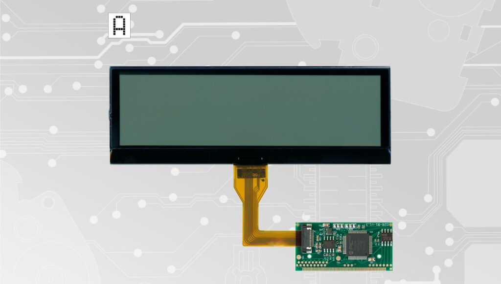
Back to product Seleziona lingua: Positive version SEPDISP28P Installation instructions for Citroën, DS, Fiat, Lancia, Peugeot, Toyota Magneti Marelli, Borg – Johnson Controls MFD display Before installing the new SEPDISP28P display, please read carefully the following instructions. Our technicians, for illustrative purposes only, have made a video tutorial about how to repair the module.DON’T SKIP ANY STEP. Watch the video tutorial Download the printable PDF WARNING: THIS PROCESS IS RECOMMENDED ONLY TO EXPERT AND QUALIFIED STAFF The display must be installed only with its related small PCB, as supplied in the original packaging; Before installing the new display SEPDISP28P, it is highly recommended to carefully read the following instructionsand watch the video below.The video is for illustrative purpose only; Do not skip any steps. THESE INSTRUCTIONS ARE FOR MAGNETI MARELLI MODULES For Borg – Johnson Controls modules, click here 1 Pic. 1 Pic. 2 De-solder the original display with a hot air de-soldering iron (Pic. 1).Clean with a solder wick to remove any excess tin (Pic. 2).A moderate amount of flux may be used to facilitate the cleaning process.Lastly, complete the cleaning with some solvent. 2 Pic. 3 IMPORTANT: positioning the board with the connector on the left, place the small PCB of the new display on the right hand-side (Pic. 3). Pic. 4 Position the small PCB leaving 1mm gap as in picture 4. 3 Solder each pin individually, one at the time, with 0,3mm thin solder wire and with conical tip at 350°C. In this case, using flux is not recommended to inexperienced staff as misusing it may damage the board irreversibly. Once soldering is completed, clean with some solvent. 4 Solder 2 jumpers between the points A-B and C-D, as highlighted inthe picture above. 5 Insert the FPC of the new display, with contacts facing down, into theconnector of the small board. 6 With a flush cutter, cut off the central clip of the plastic base of thedisplay and any other plastic part positioned by the new FPC, as it maydamage it when re-assembling. 7 Peel off the rear protective film and fit the display on its base. 8 Re-attach the board. 9 Carefully fold the FPC as shown in the picture. 10 Re-assemble the module, remove the protective film from the front side and switch it on as shown in the picture. 11 If the info are displayed clear and sharp as in the picture above, the problem is solved. Otherwise, see the section “PROBLEMS AND SOLUTIONS“.NOTE: for some cars models, the colour of the module backlight may begreen. Video Tutorial How to repair Citroën, Fiat, Lancia, Peugeot and Toyota Magneti Marelli on-board computer with Minitools SEPDISP28P LCD display THESE INSTRUCTIONS ARE FOR BORG – JOHNSON CONTROLS MODULES For Magneti Marelli modules click here 1 Pic. 5 Pic. 6 De-solder the original display with a hot air de-soldering iron (Pic. 5).Clean with a solder wick to remove any excess tin (Pic. 6). A moderateamount of flux may be used to facilitate the cleaning process.Lastly, complete the cleaning with some solvent. 2 Pic. 7 IMPORTANT: Positioning the board with the connector on the left,place the small PCB of the new display on the right hand-side (Pic. 7). Pic. 8 Position the small PCB leaving 1mm gap as in picture 8. 3 Solder each pin individually, one at the time, with 0,3mm thin solder wire andwith conical tip at 350°C. In this case, using flux is not recommended to inexperienced staff as misusing it may damage the board irreversibly. Once soldering is completed, clean with some solvent. 4 Solder 2 jumpers between the points A-B and C-D, as highlighted in the picture above. 5 With a flush cutter, cut off the central clip of the plastic base of thedisplay and any other plastic part positioned by the new FPC, as it maydamage it when re-assembling. 6 Peel off the rear protective film and fit the display on its base. 7 Insert the FPC of the new display, with contacts facing down, intothe connector of the small board. Re-assemble the module makingsure not to damage the FPC and, lastly, peel off the front film of thedisplay. 8 Switch on the module on a test bench using the Minitools CAN BUS generator SEP-RE-CAN00I.If the info are displayed clear and sharp as in the picture above, the problem is solved.Otherwise, see the section “PROBLEMS AND SOLUTIONS” beside. PROBLEMS AND SOLUTIONS (FOR MAGNETI MARELLI and BORG – JOHNSON CONTROLS) Pic. 9 If a screen as in picture 9 should appear on the display, the solderings of the small PCB may have been done wrongly; please double check them. Pic. 10 On some car models, after switching on the module, some info may appear incomplete or overlapped as in picture 10. In this case, jumper the pads with some solder as in picture 11. Pic. 11 NOTE: Once the module has been switched on, if the display doesn’t show any information, please double check the soldering points. If the problem persists even after those checks, please send a picture of the small PCB soldered onthe board at [email protected]. Minitools technicians will support you to complete the repair.
SEPDISP58: Modification for DAF CF / LF / XF display
Back to product Seleziona lingua: SEPDISP58 Modification instructions for DAF CF / LF / XF display WARNING: This process is recommended only to expert and qualified staff. Before installing the new SEPDISP58 display, please read the following instructions carefully. DO NOT SKIP ANY STEPS. Download the printable PDF Pre-facelift models Post-facelift models THE FOLLOWING MODIFICATION IS NECESSARY FOR THE CORRECT FUNCTIONING OF SEPDISP58 DISPLAY Replace the display in an ambient temperature of 25 °C. Pic. 1 Pic. 2 To adjust SEPDISP58 display voltage: After replacing the LCD, switch on the cluster with Minitools CAN-BUS generator SEP-RE-CAN007I (pic. 2).Measure the voltage between A and B points as in picture 3. • If the voltage measured is between 12.98V and 13.02V, no modification is necessary;• If the voltage detected is instead lower than 12.98V or higher than 13.02V, it is necessary to do the modification described in thefollowing paragraph “EEPROM MODIFICATION“. Measuring display voltage Pic. 3 EEPROM MODIFICATION NOTE: For this modification it is necessary to use an EEPROM programmer. We recommend our SEP-EECLIP. •First, set the programmer reading in 8 bit hexadecimal (HEX); •Desolder and make a backup of the 93C86 EEPROM (shown in picture 4); • To reach a voltage close to 13.00V act on 031E location; Please note that decreasing this location by 1 HEX unit, the variation will be +0.0189V, or vice versa. NOTE: For the version that can be used offline download the PDF. Fig. 4 If not familiar with hexadecimal calculation, it is possibile to use the calculation tool in the box below, simply typing in the values. Once these modifications have been done, measure again the voltage between A and B points and check that it actually is between 12.98V and 13.02V. If not, increase or decrease the location until the value is as close as possible to 13.00V. Pre-facelift models Post-facelift models THE FOLLOWING MODIFICATION IS NECESSARY FOR THE CORRECT FUNCTIONING OF SEPDISP58 DISPLAY. Replace the display in an ambient temperature of 25 °C. Pic. 5 Pic. 6 To adjust SEPDISP58 display voltage: After replacing the LCD, switch on the cluster with Minitools CAN-BUS generator SEP-RE-CAN007I(pic. 6). Measure the voltage between A and B points as in picture 7. • If the voltage measured is between 12.98V and 13.02V, no modification is necessary; • If the voltage detected is instead lower than 12.98V or higher than 13.02V, it is necessary to do the modification described in the following paragraph “EEPROM MODIFICATION“. Measuring display voltage Pic. 7 EEPROM MODIFICATION NOTE: For this modification it is necessary to use an EEPROM programmer. We recommend our SEP-EECLIP. •First, set the programmer reading in 8 bit hexadecimal (HEX); •Desolder and make a backup of the 24C32WP EEPROM (shown in picture 8); • To reach a voltage close to 13.00V act on 031E location; Please note that decreasing this location by 1 HEX unit, the variation will be +0.0189V, or vice versa. Pic. 4 If not familiar with hexadecimal calculation, it is possibile to use the calculation tool in the box below, simply typing in the values. Once these modifications have been done, measure again the voltage between A and B points and check that it actually is between 12.98V and 13.02V. If not, increase or decrease the location until the value is as close as possible to 13.00V.
Set of displays for Mercedes SLK dashboards: modification instructions
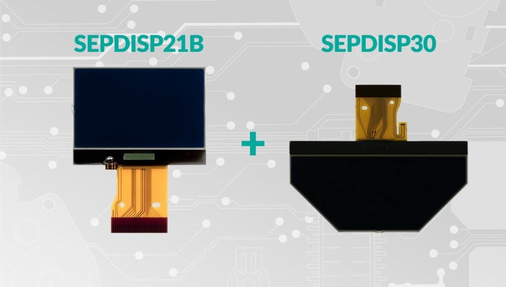
Back to product Seleziona lingua: SEPDISP21B Modification for Mercedes SLK R171 display WARNING: This process is recommended only to expert and qualified staff. Before installing the new SEPDISP21B display, please read the following instructions carefully. DO NOT SKIP ANY STEPS. Download the printable PDF THE FOLLOWING MODIFICATION IS NECESSARY FOR THE CORRECT FUNCTIONING OF SEPDISP21B DISPLAY (pic. 1). Replace the display in an ambient temperature of 25 °C Pic. 1 Pic. 2 To adjust SEPDISP21B display voltage: After replacing the LCD, switch on the cluster with the Minitools connector SEP-PA011.Measure the voltage between A and B points as in picture 3.· If the voltage measured is between 11.98V and 12.02V, no modification is necessary;· If the voltage detected is instead lower than 11.98V or higher than 12.02V, it is necessary to do the modification described in thefollowing paragraph “EEPROM MODIFICATION ”. Measuring display voltage . Pic. 3 modifica eeprom NOTE: For this modification it is necessary to use an EEPROM programmer. We recommend our SEP-EECLIP. •First, set the programmer reading in 8 bit hexadecimal (HEX). • Desolder and make a backup of the 24C16 EEPROM (shown in picture 4) • To reach a voltage close to 12.00V act on 02D8 location Please note that decreasing this location by 1 HEX unit, the variation will be + 0.016V, or vice versa. NOTE: For the oflline version download PDF. Pic. 4 If not familiar with hexadecimal calculation, it is possibile to use the calculation tool in the box below, simply typing in the values. Once these modifications have been done, measure again the voltage between A and B points and check that it actually is between 11.98V and 12.02V. If not, increase or decrease the location until the value is as close as possible to the right range. SEPDISP30 Modification for Mercedes SLK R171 display WARNING: This process is recommended only to expert and qualified staff. Before installing the new SEPDISP30 display, please read carefully the following instructions. DON’T SKIP ANY STEP. Download the printable PDF THE FOLLOWING MODIFICATION IS NECESSARY FOR THE CORRECT FUNCTIONING OF SEPDISP21B DISPLAY (pic. 1) Replace the display in an ambient temperature of 25 °C. Pic. 1 Pic. 2 To adjust SEPDISP30 display voltage: After replacing the LCD, switch on the cluster with the Minitools connector SEP-PA011. Measure the voltage between A and B points as in picture 3. • If the voltage measured is between 12.08V and 12.12V, no modification is necessary;• If the voltage detected is instead lower than 12.08V or higher than 12.12V, it is necessary to do the modification described in the following paragraph “EEPROM MODIFICATION“. Measuring display voltage Pic. 3 EEPROM MODIFICATION NOTE: For this modification it is necessary to use an EEPROM programmer. We recommend our SEP-EECLIP. • First, set the programmer reading in 8 bit hexadecimal (HEX); • Desolder and make a backup of the 24C16 EEPROM (shown in picture 4); • To reach a voltage close to 12.1V act on 02B8 location. Please note that decreasing this location by 1 HEX unit, the variation will be + 0.016V, or vice versa. NOTE: For the oflline version download PDF. Pic. 4 If not familiar with hexadecimal calculation, it is possibile to use the calculation tool in the box below, simply typing in the values. Once these modifications have been done, measure again the voltage between A and B points and check that it actually is between 12.08V and 12.12V. If not, increase or decrease the location until the value is as close as possible to the right range.
SEPDISP14: Modification for Renault Modus LCD display
Back to product Seleziona lingua: SEPDISP14 Modification for Renault Modus display WARNING: THIS PROCESS IS RECOMMENDED ONLY TO EXPERT AND QUALIFIED STAFF. Before installing the new SEPDISP14 display, please read the following instructions carefully. DO NOT SKIP ANY STEPS. Download the printable PDF THE FOLLOWING MODIFICATION IS NECESSARY FOR THE CORRECT FUNCTIONING OF SEPDISP14 LCD DISPLAY Replace the display in an ambient temperature of 25 °C. After replacing the LCD, switch on the cluster on a test bench with the CAN-BUS generator SEP-CAN-MODUS to measure the voltage between the points A and B (see picture 1). Alternatively, it is possible to switch on the module directly on the car, but this second option is not recommended. If the voltage measured is between 8,10V and 8,30V no modification is needed. If the voltage is, instead, lower than 8.10V or higher than 8,30V the modification is necessary. The operations to carry out are explained in the following paragraph “EEPROM MODIFICATION“, and distinguished according to the code of EEPROM on the PCB (see picture 2), the 93C66 or the 93C56. Picture 1 Picture 2 Modification for eeprom 93c66 NOTE: For this modification, it is necessary to use an EEPROM programmer We recommend our SEP-EECLIP. De-solder the EEPROM 93C66 highlighted in picture 2, located on the PCB; First, set the programmer reading in 8 bit hexadecimal (HEX); ATTENTION: Make a backup of the EEPROM, before the modification. To reach a voltage between 8,10V and 8,30V, identify the locations 001D and 0027 and modify their values: increasing or decreasing the values by 1 HEX unit, the variation will be +/- 0.09V. If not familiar with hexadecimal calculation, it is possible to use the calculation tool in the box below, simply typing in the values. Verification Once these operations have been done, save the file just modified and upload it on the EEPROM. Solder back the 93C66 EEPROM on the PCB, switch on the instrument cluster and check again the tension between points A and B (see picture 1). Verify, then, if a voltage between 8,10V and 8,30V has actually been reached. If not, decrease or increase the values of the locations until the voltage is between that range. Modification for eeprom 93c56 NOTE: For this modification, it is necessary to use an EEPROM programmer We recommend our SEP-EECLIP. De-solder the EEPROM 93C56 highlighted in picture 2, located on the PCB; First, set the programmer reading in 8 bit hexadecimal (HEX); ATTENTION: Make a backup of the EEPROM, before the modification. To reach a voltage between 8,10V and 8,30V, identify the locations 00F7 and 00FD and modify their values: increasing or decreasing the values by 1 HEX unit, the variation will be +/- 0.09V. If not familiar with hexadecimal calculation, it is possible to use the calculation tool in the box below, simply typing in the values. Verification Once these operations have been done, save the file just modified and upload it on the EEPROM. Solder back the 93C56 EEPROM on the PCB, switch on the instrument cluster and check again the tension between points A and B (see picture 1). Verify, then, if a voltage between 8,10V and 8,30V has actually been reached. If not, decrease or increase the values of the locations until the voltage is between that range.
SEPDISP56: Installation and modification for Porsche 987 and 997 LCD display

Back to product Seleziona lingua: SEPDISP56 Porsche 987 and 997 display installation WARNING! The repair should be carried out only by qualified and competent staff. Before installing the new SEPDISP28N display, please read carefully the following instructions. Our technicians, for illustrative purposes only, have made a video tutorial about how to repair the odometer. DON’T SKIP ANY STEP. Watch the video tutorial Download the printable PDF INSTALLATION OF THE DISPLAY “SEPDISP56” AND OF THE BACKLIGHT SHEET Replace the display in an ambient temperature of 25 °C. Replace the backlight placed under the original LCD with the one supplied with the Minitools part to avoid chromatic discrepancies. Replace the backlight placed under the original LCD with the one supplied with the Minitools part to avoid chromatic discrepancies. To watch it, click on the button below. Video 1 Remove the original display. 2 Undo and remove the diffuser and the pink original backlight. 3 Fit and secure the new Minitools backlight. 4 Re-insert the diffuser. 5 Fit the new Minitools display After replacing the LCD, switch on the cluster (pin nº 1 negative, pin nº 2 positive) and, with a multimeter, measure the voltage on the PCB on which the display is connected, between the points A and B indicated in picture 1. If the voltage measured is between 11,95 V and 12,05 V, no modification is necessary; If the voltage detected is, instead, lower than 11,95V or higher than 12,05V, it is necessary to do the modification described in the following paragraph “EEPROM MODIFICATION“. EEPROM MODIFICATION NOTE: For this modification it is necessary to use an EEPROM programmer. We recommend our SEP-EECLIP. • First, set the programmer reading in 8 bit hexadecimal (HEX) . • De-solder the 93LC86 EEPROM (highlighted in picture 2), which is located inside the metal enclosure on the rear side of the display PCB. • ATTENTION: Make a backup of the de-soldered EEPROM, before the modification. • To reach a voltage between 11,95V and 12,05V, it is necessary to modify the value of the location 0240. Please note that decreasing these locations by 1 HEX unit, the variation will be +0,00625V, or vice versa. If not familiar with hexadecimal calculation, it is possible to use the calculation tool in the box beside, simply typing in the values. VERIFICATION Once these modifications have been done, measure again the voltage between the points A and B and check that it actually is between 11,95V and 12,05V. If not, increase or decrease the location until the value is as close as possible to the correct range. Video Tutorial How to replace Porsche 911 997, Boxster 987 and Cayman 987 instrument clusters faulty LCD display
SEPDISP13: Modification for Peugeot 407 and 607 instrument clusters display
Back to product Seleziona lingua: SEPDISP13 Modification for Peugeot 407 and 607 instrument clusters display Before installing the new SEPDISP13 display, please read the following instructions carefully. For illustration purposes, our technicians have made a video tutorial on how to repair the odometer. DO NOT SKIP ANY STEPS. Watch the video tutorial Download printable PDF Warning: this process is recommended only to expert and qualified staff The following modification is necessary for the correct functioning of SEPDISP13 display. • Replace the display in an ambient temperature of 25 °C• After replacing the LCD, switch on the cluster (pin no. 16 positive, pin no. 18 negative) and measure the voltage between A and B points (Pic.1).• If the voltage measured is between 6.3V and 6.4V, no modification is necessary;• If the voltage detected is instead lower than 6.3V or higher than 6.4V, it is necessary to do the modification described in the following paragraph “EEPROM MODIFICATION”. Pic. 1 Eeprom modification NOTE: For this modification, it is necessary to use an EEPROM programmer. We recommend our SEP-EECLIP. • De-solder the EEPROM 93C66 located on the PCB (Pic. 1); •First, set the programmer reading in 8 bit hexadecimal (HEX). ATTENTION: make a backup of the EEPROM, before the modification. • To reach a voltage between 6.3V and 6.4V, identify the 0122, 0123, 0124, 0125, 0126 and 0127 locations and modify their values: increasing or decreasing the 6 values by 1 HEX unit, the variation will be +/- 0.10 V. If not familiar with hexadecimal calculation, it is possible to use the calculation tool in the box beside, simply typing in the values. NOTE: For the version that can be used offline, download the PDF. Verification Once these operations have been done, solder back the 93C66 EEPROM on the PCB, switch on the instrument cluster and check again the tension between points A and B. Verify, then if a voltage between 6.3V and 6.4V has actually been reached. If not, decrease or increase the values of the locations until the voltage is between that range. Video Tutorial How to replace Peugeot 407 dashboard display with Minitools SEPDISP13 LCD screen
SEPDISP30: Modification for Mercedes SLK R171 display
Back to product Seleziona lingua: SEPDISP30 Modification for Mercedes SLK R171 display WARNING: This process is recommended only to expert and qualified staff. Before installing the new SEPDISP33 display, please read carefully the following instructions. DON’T SKIP ANY STEP. Download the printable PDF THE FOLLOWING MODIFICATION IS NECESSARY FOR THE CORRECT FUNCTIONING OF SEPDISP21B DISPLAY (pic. 1) Replace the display in an ambient temperature of 25 °C. Pic. 1 Pic. 2 To adjust SEPDISP30 display voltage: After replacing the LCD, switch on the cluster with Minitools connector SEP-PA011. Measure the voltage between A and B points as in picture 3. • If the voltage measured is between 12.08V and 12.12V, no modification is necessary;• If the voltage detected is instead lower than 12.08V or higher than 12.12V, it is necessary to do the modification described in the following paragraph “EEPROM MODIFICATION“. Measuring display voltage Pic. 3 EEPROM MODIFICATION NOTE: For this modification it is necessary to use an EEPROM programmer. We recommend our SEP-EECLIP. • First, set the programmer reading in 8 bit hexadecimal (HEX); • Desolder and make a backup of the 24C16 EEPROM (shown in picture 4); • To reach a voltage close to 12.1V act on 02B8 location. Please note that decreasing this location by 1 HEX unit, the variation will be + 0.016V, or vice versa. NOTE: For the oflline version download PDF. Pic. 4 If not familiar with hexadecimal calculation, it is possibile to use the calculation tool in the box below, simply typing in the values. Once these modifications have been done, measure again the voltage between A and B points and check that it actually is between 12.08V and 12.12V. If not, increase or decrease the location until the value is as close as possible to the right range.
SEPDISP21B: Modification for Mercedes SLK R171 display
Back to product Seleziona lingua: SEPDISP21B Modification for Mercedes SLK R171 display WARNING: This process is recommended only to expert and qualified staff. Before installing the new SEPDISP21B display, please read carefully the following instructions.DON’T SKIP ANY STEP. Download the printable PDF THE FOLLOWING MODIFICATION IS NECESSARY FOR THE CORRECT FUNCTIONING OF SEPDISP21B DISPLAY (pic. 1). Replace the display in an ambient temperature of 25 °C Pic. 1 Pic. 2 To adjust SEPDISP21B display voltage: After replacing the LCD, switch on the cluster with the Minitools connector SEP-PA011. Measure the voltage between A and B points as in picture 3. · If the voltage measured is between 11.98V and 12.02V, no modification is necessary; · If the voltage detected is instead lower than 11.98V or higher than 12.02V, it is necessary to do the modification described in the following paragraph “MODIFICA EEPROM”. Measuring display voltage . Pic. 3 EEPROM MODIFICATION NOTE: For this modification it is necessary to use an EEPROM programmer. We recommend our SEP-EECLIP. •First, set the programmer reading in 8 bit hexadecimal (HEX). • Desolder and make a backup of the 24C16 EEPROM (shown in picture 4) • To reach a voltage close to 12.00V act on 02D8 location Please note that decreasing this location by 1 HEX unit, the variation will be + 0.016V, or vice versa. NOTE: For the oflline version download PDF. Pic. 4 If not familiar with hexadecimal calculation, it is possibile to use the calculation tool in the box below, simply typing in the values. Once these modifications have been done, measure again the voltage between A and B points and check that it actually is between 11.98V and 12.02V. If not, increase or decrease the location until the value is as close as possible to the right range.
SEPDISP08-7V: Modification for Mercedes A-Class and B-Class dashboard display
Back to product Seleziona lingua: SEPDISP08-7V Modification for Mercedes A and B Class instrument clusters display Before installing the new SEPDISP08-7V display, please read carefully the following instructions. Our technicians, for illustrative purposes only, have made a video tutorial about how to repair the instrument panel.DON’T SKIP ANY STEP. Watch the video tutorial Download the printable PDF NOTE:The following instructions are only for SEPDISP08-7V displays with the warranty code printed on a label attached on the FPC (see the picture beside). ATTENTION!If the code is, instead, marked directly on the FPC, please contact us. NOTE:The following instructions are only for SEPDISP08-7V displays with the warranty code printed on a label attached on the FPC (see the picture below). ATTENTION!If the code is, instead, marked directly on the FPC, please contact us. WARNING: THIS PROCESS IS RECOMMENDED ONLY TO EXPERT AND QUALIFIED STAFF THE FOLLOWING MODIFICATION IS NECESSARY FOR THE CORRECT FUNCTIONING OF SEPDISP08-7V DISPLAY. • Replace the display in an ambient temperature of 25 °C. • After replacing the LCD, switch on the cluster (pin no. 1 negative, pin no. 5 and no. 6 positive) and measure the voltage between A and B points as in picture 1. • If the voltage measured is between 6.45V and 6.55V no modification is necessary; • If the voltage detected is instead lower than 6.45V or higher than 6.55V, it is necessary to do the modification described in the following paragraph “EEPROM MODIFICATION“. Picture 1 EEPROM MODIFICATION NOTE: For this modification, it is necessary to use an EEPROM programmer.We recommend our SEP-EECLIP. • De-solder the EEPROM (24C04 or 24C32), highlighted in picture 2, located on the PCB.• First, set the programmer reading in 8 bit hexadecimal (HEX).• ATTENTION: Make a backup of the EEPROM, before the modification.• To reach a voltage between 6.45V and 6.55V, identify the 01BF and 01CF locations and modify their values: increasing or decreasing the 2 values by 1 HEX unit, the variation will be +/- 0.09V. If not familiar with hexadecimal calculation, it is possible to use the calculation tool in the box beside, simply typing in the values. NOTE: For the version that can be used offline download the PDF. VERIFICATION Once these operations have been done, solder back the EEPROM on the PCB,switch on the instrument cluster and check again the tension between points A and B (see picture 1). Verify, then, if a voltage between 6.45V and 6.55V has actually been reached. If not, decrease or increase the values of the locations until the voltage is between that range. Picture 2 Video Tutorial Mercedes A-Class W169 and B-Class W245 instrument panel repair with Minitools SEPDISP08-7V LCD display
SEPDISP27: Modification for Porsche Cayenne Mk1 and Volkswagen Touareg Mk1 display

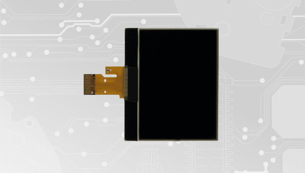
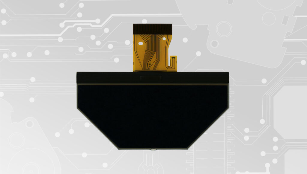
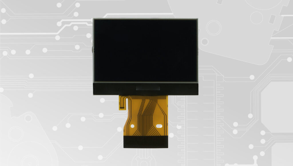
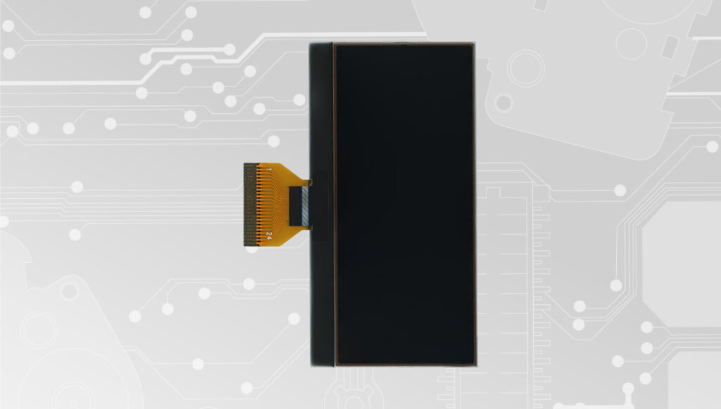
Back to product Seleziona lingua: SEPDISP27 Modification for Porsche Cayenne and Volkswagen Touareg LCD display WARNING: This process is recommended only to expert and qualified staf Before installing the new SEPDISP27 display, please read the following instructions carefully. DO NOT SKIP ANY STEPS. Watch the video tutorial Download printable PDF NOTE: The following instructions are for SEPDISP27 displays marked with D27A02XXXX serial numbers on the FPC (see picture beside). • Replace the display in an ambient temperature of 25 °C. • After replacing the LCD, switch on the cluster (pin no. 1 positive, pin no. 24 negative) • If you have a multimeter with needle probes, measure the voltage between A and B points on the rear of the board (see picture 1), OTHERWISE remove the pointers and the front panel and measure the voltage between A and B points on the front part of the board (see picture 2). Fig. 1 Fig. 2 Fig. 3 • If the voltage measured is between 7,0V and 7,2V, no modification is necessary; • If the voltage detected is instead lower than 7,0V or higher than 7,2V, it is necessary to do the modification described in the following paragraph “EEPROM MODIFICATION“ EEPROM MODIFICATION NOTE: For this modification on the instrument clusters, it is necessary to use an EEPROM programmer. We recommend our SEP-EECLIP. • First, set the programmer reading in 8 bit hexadecimal (HEX). • Make a backup of the 24C08 EEPROM, which is on the cluster (picture 3). To reach a voltage between 7,0V and 7,2V, it is necessary to modify the value of 0320 location OR the one of 0343 location; to identify which location to act on, locate the group of 3 consecutive values: “14, 28, 78”. The value to be modified is always the one before the group just mentioned. Please note that increasing or decreasing these locations by 1 HEX unit, the variation will be +/- 0.1V. If not familiar with hexadecimal calculation, it is possible to use the calculation tool in the box beside, simply typing in the values. Once these modifications have been done, measure again the voltage between A and B points and check that it actually is between 7,0V and 7.2V. If not, increase or decrease the location until the value is as close as possible to the right range. Video Tutorial How to repair Volkswagen Touareg Mk1 and Porsche Cayenne Mk1 dashboards with Minitools SEPDISP27 LCD display