THE FOLLOWING MODIFICATION IS NECESSARY FOR THE CORRECT FUNCTIONING OF SEPDISP58 DISPLAY
Replace the display in an ambient temperature of 25 °C.
Pic. 1
Pic. 2
To adjust SEPDISP58 display voltage:
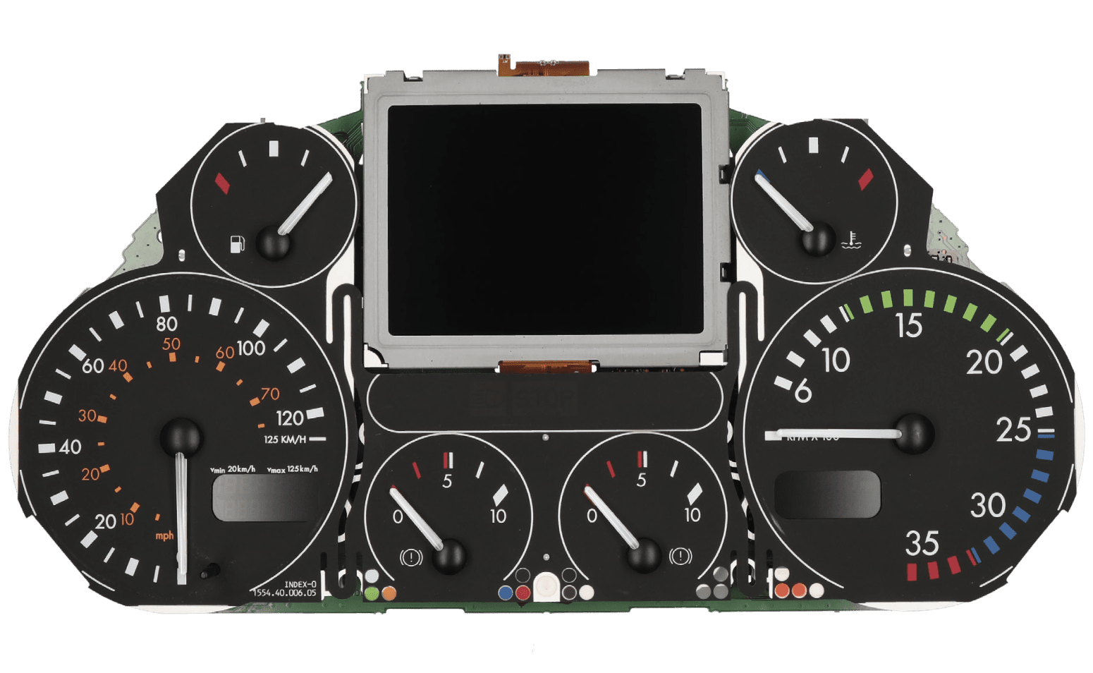
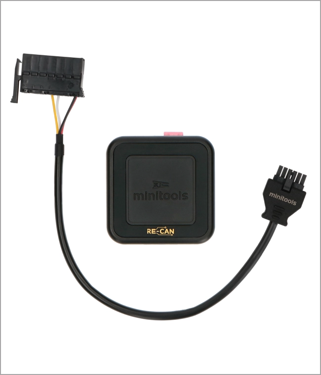
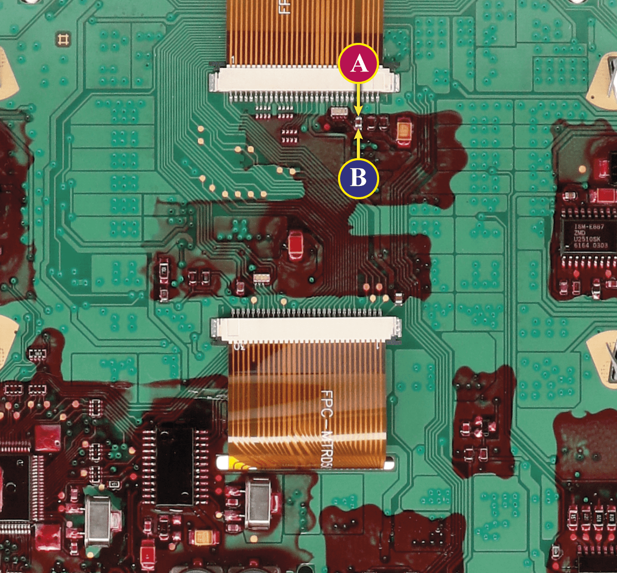
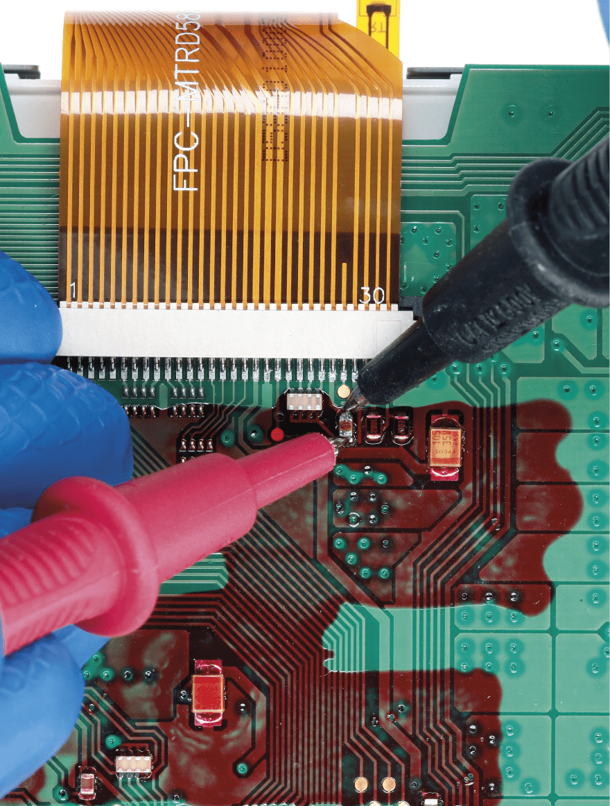
After replacing the LCD, switch on the cluster with Minitools CAN-BUS generator SEP-RE-CAN007I (pic. 2). Measure the voltage between A and B points as in picture 3.
• If the voltage measured is between 12.98V and 13.02V, no modification is necessary; • If the voltage detected is instead lower than 12.98V or higher than 13.02V, it is necessary to do the modification described in the following paragraph “EEPROM MODIFICATION“.
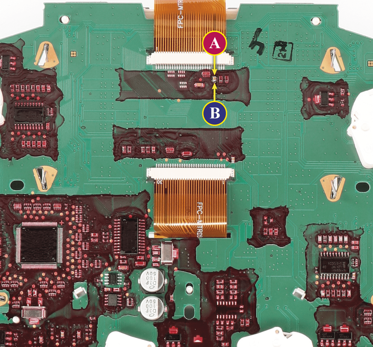
Measuring display voltage
Pic. 3
EEPROM MODIFICATION
NOTE: For this modification it is necessary to use an EEPROM programmer.
We recommend our SEP-EECLIP.
•First, set the programmer reading in 8 bit hexadecimal (HEX);
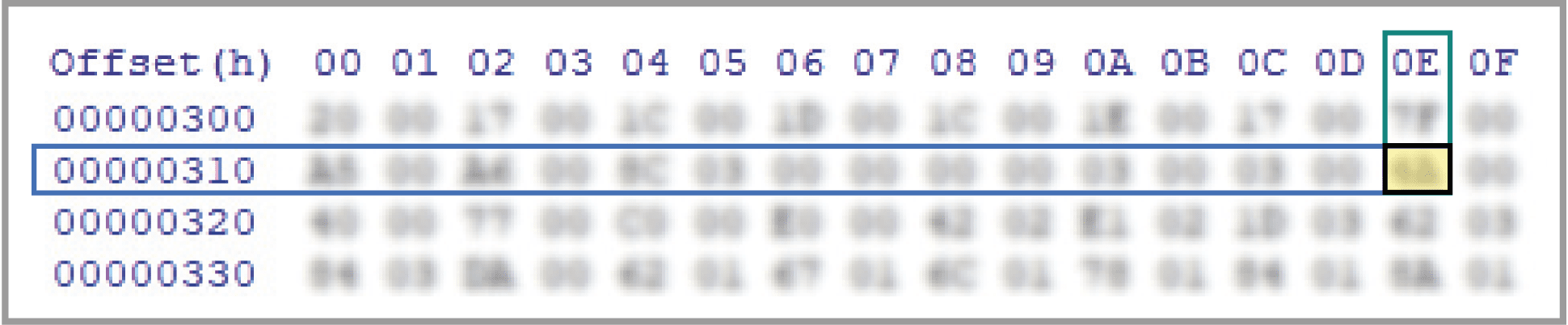
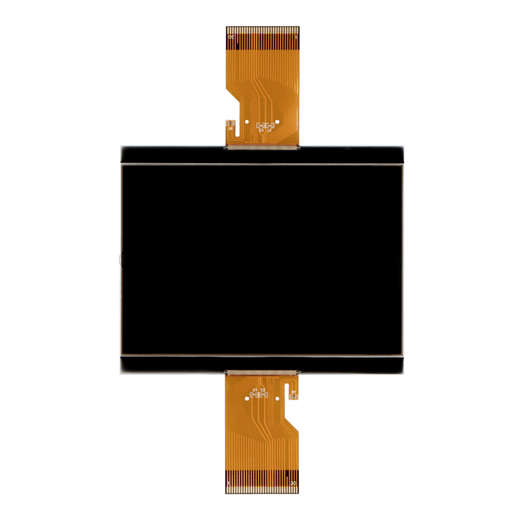
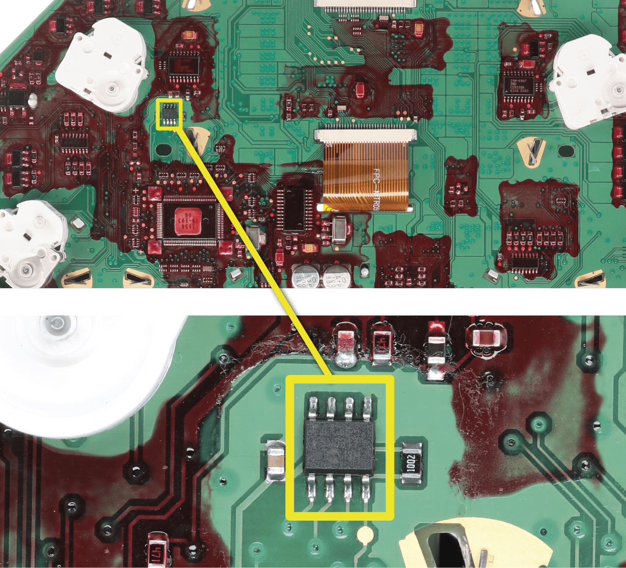
•Desolder and make a backup of the 93C86 EEPROM (shown in picture 4); • To reach a voltage close to 13.00V act on 031E location;
Please note that decreasing this location by 1 HEX unit, the variation will be +0.0189V, or vice versa.
NOTE: For the version that can be used offline download the PDF.
Fig. 4
If not familiar with hexadecimal calculation, it is possibile to use the calculation tool in the box below, simply typing in the values.
Calculation SEPDISP58
CALCULATION OF THE NEW VALUES OF THE LOCATIONS
*How to identify 031E location value on the EEPROM programmer
Once these modifications have been done, measure again the voltage between A and B points and check that it actually is between 12.98V and 13.02V. If not, increase or decrease the location until the value is as close as possible to 13.00V.
THE FOLLOWING MODIFICATION IS NECESSARY FOR THE CORRECT FUNCTIONING OF SEPDISP58 DISPLAY.
Replace the display in an ambient temperature of 25 °C.
Pic. 5
Pic. 6
To adjust SEPDISP58 display voltage:
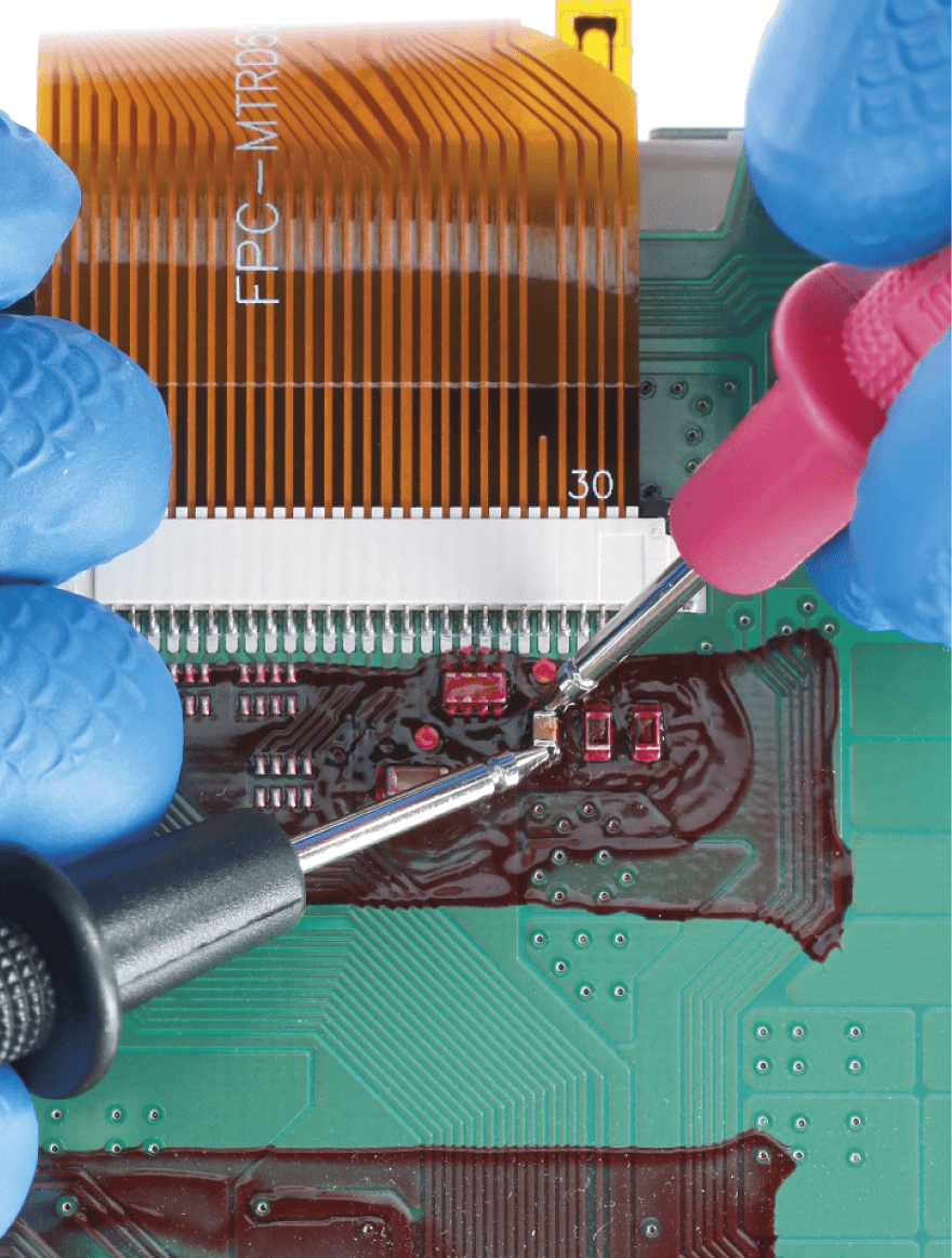
After replacing the LCD, switch on the cluster with Minitools CAN-BUS generator SEP-RE-CAN007I(pic. 6). Measure the voltage between A and B points as in picture 7.
• If the voltage measured is between 12.98V and 13.02V, no modification is necessary;
• If the voltage detected is instead lower than 12.98V or higher than 13.02V, it is necessary to do the modification described in the following paragraph “EEPROM MODIFICATION“.
Measuring display voltage
Pic. 7
EEPROM MODIFICATION
NOTE: For this modification it is necessary to use an EEPROM programmer.
We recommend our SEP-EECLIP.
•First, set the programmer reading in 8 bit hexadecimal (HEX);
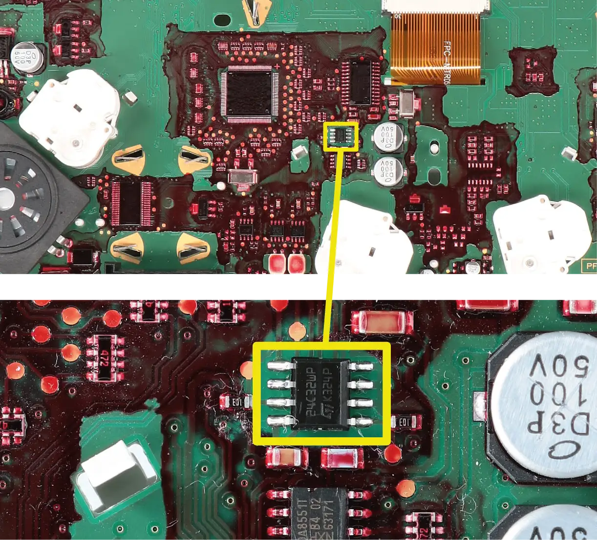
•Desolder and make a backup of the 24C32WP EEPROM (shown in picture 8); • To reach a voltage close to 13.00V act on 031E location;
Please note that decreasing this location by 1 HEX unit, the variation will be +0.0189V, or vice versa.
Pic. 4
If not familiar with hexadecimal calculation, it is possibile to use the calculation tool in the box below, simply typing in the values.
Calculation SEPDISP58
CALCULATION OF THE NEW VALUES OF THE LOCATIONS
*How to identify 031E location value on the EEPROM programmer
Once these modifications have been done, measure again the voltage between A and B points and check that it actually is between 12.98V and 13.02V. If not, increase or decrease the location until the value is as close as possible to 13.00V.