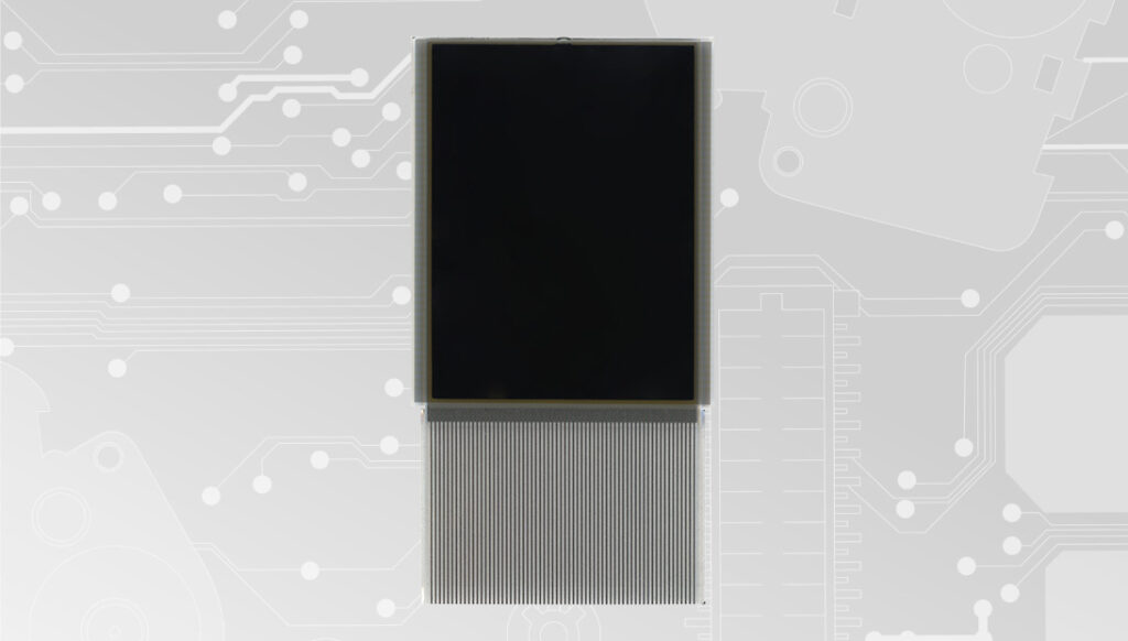
SEPDISP45: Installation instructions

Back to product Seleziona lingua: SEPDISP45 Modification instructions Before installing the new SEPDISP45 display, please read the following instructions carefully. DO NOT SKIP ANY STEPS. Download printable PDF 1 Remove the original display. 2 Peel the adhesive film off the back as shown in the photo. 3 Apply the film to the back of the new Minitools display, making sure it adheres perfectly the SEPDISP45 display. 4 Once this operation is complete, insert the press-fit display into the dedicated connector on the main board. SEPDISP45 | VERS. 3.0
SEPDISP40: Modification instructions for Audi A4 B5 display
Back to product Seleziona lingua: SEPDISP40 Modification instructions for Audi A4 B5 display WARNING: THIS PROCESS IS RECOMMENDED ONLY TO EXPERT AND QUALIFIED STAFF Before installing the new SEPDISP40 display, please read the following instructions carefully.DO NOT SKIP ANY STEPS. Download the printable PDF Seal the flat cable of the new display on the PCB of the instrument cluster with a soldering iron with “T” tip at 350° C Pic. 1 Fit the display on its base and position the frame supplied with the kit as in picure 1. Lastly, overlap the original metal frame as in picture 2. Pic. 2
SEPDISP17B: Modification instructions
Back to product Seleziona lingua: SEPDISP17B Modification instructions NOTES: A good level of skill and soldering experience are required to replace the display. Watch the video tutorial Download the printable PDF THE FOLLOWING MODIFICATION IS NECESSARY FOR THE CORRECT FUNCTIONING OF SEPDISP17B DISPLAY After replacing the LCD, identify the resistor shown in picture 1, de-solder it and replace it with one by 2.7K ohm (2 resistors are supplied with the Minitools kit, 1 of which is extra). Test POWER SUPPLY: • Pin 7, Pin 14: +12V; • Pin 8: GND. Video Tutorial Mercedes Vito W639, Viano W639 and Viano Marco Polo W639 speedometer repair using Minitools SEPDISP17B display
SEPDISP04 kit supplied: Modification instructions for Alfa Romeo 156/147 display

Back to product Seleziona lingua: SEPDISP04 supplied with modification kit Modification instructions for Alfa Romeo 156/147 display ALFA ROMEO 156 INFOCENTER ALFA ROMEO 147 CAR STEREO SAT NAV WARNING: THE FOLLOWING OPERATIONS ARE RECOMMENDED TO QUALIFIED STAFF ONLY. Before installing the new SEPDISP04 display, please read the following instructions carefully. DO NOT SKIP ANY STEPS. Download the printable PDF ALFA ROMEO 156 INFOCENTER DISPLAY VISUALIZATION CHECK Pic. 1 After installing the new Minitools display, switch on the infocenter (pic. 1) and check that the information shown is sharp as in pic. 2. If not, follow all steps at section “ALFA ROMEO 156 INFOCENTER “. Pic. 2 ALFA ROMEO 147 SAT NAV DISPLAY VISUALIZATION CHECK Pic. 3 After installing the new Minitools display, switch on the sat-nav (pic. 3) and check that the information shown is sharp as in pic. 4. If not, follow all steps at section “ALFA ROMEO 147 SET NAV“ Pic. 4 Alfa romeo 156 infocenter NOTE: For ALFA ROMEO 147 CAR RADIO/SAT NAV, click here. WARNING: THE FOLLOWING OPERATIONS ARE RECOMMENDED TO QUALIFIED STAFF ONLY. 1 Pic. 5 Remove the Minitools display and the resistor highlighted in picture 5. 2 Pic. 6 Position the trimmer (supplied with the kit) in the area indicated in picture 6, securing it with the double-sided adhesive tape on its back. 3 Pic. 7 Pic. 8 Solder trimmer terminal 3 to point A (GND) (pic.7) and install a jumper between terminal 2 and point B, placed on the back of the board (pic. 8). 4 Pic. 9 Pic. 10 Reconnect the Minitools display as in picture 9 and switch on the infocenter (pic. 10). 5 While the module is on, act on the trimmer wheel to adjust the display visualization. 6 Check if the display is sharp. If not, act again on the trimmer wheel until the required sharpness is reached. ALFA ROMEO 147 CAR RADIO/SAT NAV NOTE: Fot ALFA ROMEO 156 INFOCENTER, click here. WARNING: THE FOLLOWING OPERATIONS ARE RECOMMENDED TO QUALIFIED STAFF ONLY. 1 Remove the Minitools display and the resistor highlighted in picture 11. Pic. 11 2 Pic. 12 Solder the cable supplied with the kit (picture 12) to terminal 3 of the trimmer and insulate with its heat shrink sleeve. 3 Position the trimmer in the area shown in picture 13 and secure it with the double-sided adhesive tape on the back. Pic. 13 4 Connect two jumpers, one between terminal 2 and point C and the other between terminal 3 and point D (pic. 4). Pic. 14 5 Pic. 15 Reconnect the Minitools display and switch on the sat-nav (picture 15). 6 While the module is on, act on the trimmer wheel to adjust the display visualization. 7 Check if the display is sharp. If not, act again on the trimmer wheel until the required sharpness is reached.
SEPCOV2: Repair guide

Back to product Seleziona lingua: SEPCOV2 Repair guide ATTENTION: THESE OPERATIONS ARE ONLY RECOMMENDED FOR EXPERIENCED PERSONNEL. Before repairing the SEI-MOT01 motor, we strongly recommend that you carefully follow the instructions below. As an example, our technicians have made a video tutorial on how to carry out the repair of the motor: follow the video below. Do not leave out any steps. Before repairing the SEI-MOT01B motor, we strongly recommend that you carefully follow the instructions below. As an example, our technicians have made a video tutorial on how to carry out the repair of the motor: follow the video below. Do not leave out any steps. Watch the video tutorial Download the printable PDF Cover for repairing stepper motors Replacement guide 1 2 3 4 5 Video Tutorial SEI-MOT01 How to repair the needle stepper motor of Audi, Citroën, Fiat, Lancia, Peugeot, Renault, Volkswagen, Aprilia, Ducati and Yamaha Video Tutorial SEI-MOT01B How to repair the pointer motor of Citroën, Fiat, Lancia, Mercedes and Peugeot instrument clusters
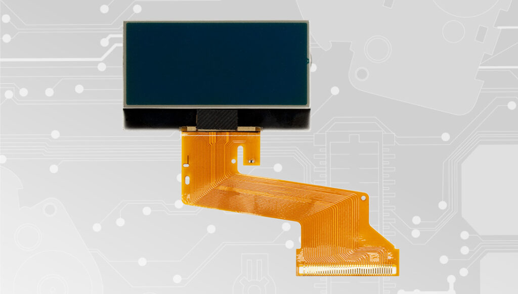
SEI-DISP237: Mercedes W208, W210, W463 voltage measurement
Back to product Seleziona lingua: SEI-DISP237 Mercedes W208, W210, W463 voltage measurement Warning: it is necessary to measure and tell us the voltage as shown before purchasing Before installing the new SEI-DISP237 display, please read the following instructions carefully. DO NOT SKIP ANY STEPS. Download the printable PDF Picture 1 Picture 2 TO MEASURE THE VOLTAGE remove the rear cover of the instrument cluster to reach the PCB; switch on the dashboard (left connector -> Pin A03 and A12 negative, A09 and A11 positive) as in picture 2; measure the voltage between A and B points as shown in pictures 3 and 4; send us an e-mail at [email protected] with the voltage measured. Voltage measurement Picture 3 Picture 4
SEPDISP28N: Installation instructions for Citroën, DS, Fiat, Lancia, Peugeot, Toyota Magneti Marelli MFD display
Back to product Seleziona lingua: Negative version SEPDISP28N Installation instructions for Citroën, DS, Fiat, Lancia, Peugeot, Toyota Magneti Marelli MFD display Before installing the new SEPDISP28N display, please read carefully the following instructions. Our technicians, for illustrative purposes only, have made a video tutorial about how to repair the odometer.DON’T SKIP ANY STEP. Watch the video tutorial Download the printable PDF WARNING: THIS PROCESS IS RECOMMENDED ONLY TO EXPERT AND QUALIFIED STAFF The display must be installed only with its related small PCB, as supplied in the original packaging; Before installing the new display SEPDISP28N, it is highly recommended to carefully read the following instructions and watch the video below. Do not skip any steps. THESE INSTRUCTIONS ARE FOR MAGNETI MARELLI MODULES For Borg – Johnson Controls modules click here 1 Pic. 1 Pic. 2 De-solder the original display with a hot air de-soldering iron (Pic. 1). Clean with a solder wick to remove any excess tin (Pic. 2). A moderate amount of flux may be used to facilitate the cleaning process. Lastly, complete the cleaning with some solvent. 2 Pic. 3 IMPORTANT: positioning the board with the connector on the left, place the small PCB of the new display on the right hand-side (Pic. 3). Pic. 4 Position the small PCB leaving 1mm gap as in picture 4. 3 Solder each pin individually, one at the time, with 0,3mm thin solder wire and with conical tip at 350°C. In this case, using flux is not recommendedto inexperienced staff as misusing it may damage the board irreversibly. Once soldering is completed, clean with some solvent 4 Solder 2 jumpers between the points A-B and C-D, as highlighted in the picture above. 5 Insert the FPC of the new display, with contacts facing down, into the connector of the small board. 6 With a flush cutter, cut off the central clip of the plastic base of the display and any other plastic part positioned by the new FPC, as it may damage it when re-assembling. Position the frame supplied with the kit on the backlight diffuser underneath the display. 7 Peel off the rear protective film and fit the display on its base. Re-attach the board. Carefully fold the FPC as shown in the picture. 8 Re-assemble the module, remove the protective film from the front side and switch it on as shown in the picture. 9 If the info are displayed clear and sharp as in the picture above, the problemis solved. Otherwise, see the section “PROBLEMS AND SOLUTIONS“. Video Tutorial How to repair Citroën, Fiat, Lancia, Peugeot and Toyota Magneti Marelli on-board computer with Minitools SEPDISP28P LCD display The above video is not related to SEPDISP28N, but illustrative of assembly techniques; WARNING: THIS PROCESS IS RECOMMENDED ONLY TO EXPERT AND QUALIFIED STAFF The display must be installed only with its related small PCB, as supplied in the original packaging; Before installing the new display SEPDISP28N, it is highly recommended to carefully read the following instructions and watch the video below. Do not skip any steps. THESE INSTRUCTIONS ARE FOR BORG – JOHNSON CONTROLS MODULES For Magneti Marelli modules click here 1 Pic. 5 Pic. 6 De-solder the original display with a hot air de-soldering iron (Pic. 5). Clean with a solder wick to remove any excess tin (Pic. 6). A moderate amount of flux may be used to facilitate the cleaning process. Lastly, complete the cleaning with some solvent. 2 Pic. 7 IMPORTANT: Positioning the board with the connector on the left, place the small PCB of the new display on the right hand-side (Pic. 7). Pic. 8 Position the small PCB leaving 1mm gap as in picture 8 3 Solder each pin individually, one at the time, with 0,3mm thin solder wire andwith conical tip at 350°C, using flux is not recommended to inexperienced staff as misusing it may damage the board irreversibly. Once soldering is completed, clean with some solvent. 4 Solder 2 jumpers between the points A-B and C-D, as highlighted in the picture above. 5 With a flush cutter, cut off the central clip of the plastic base of the display and any other plastic part positioned by the new FPC, as it may damage it when re-assembling. 6 Position the frame supplied with the kit on the backlight diffuser underneaththe display. 7 Peel off the rear protective film and fit the display on its base. 8 Insert the FPC of the new display, with contacts facing down, into theconnector of the small board. Re-assemble the module making sure not todamage the FPC and, lastly, peel off the front film of the display. 9 Switch on the module on a test bench using the Minitools CAN BUS generator SEP-RE-CAN008I.If the info are displayed clear and sharp as in the picture above, the problemis solved.Otherwise, see the section “PROBLEMS AND SOLUTIONS” beside. PROBLEMS AND SOLUTIONS (For MAGNETI MARELLI and BORG – JOHNSON CONTROLS) Pic. 9 If a screen as in picture 9 should appear on the display, the solderings of the small PCB may have been done wrongly; please doublecheck them. Pic. 10 On some car models, after switching on the module, some info may appear incomplete or overlapped as in picture 10. In this case, jumper the pads with some solder as in picture 11. Pic. 11 NOTE: Once the module has been switched on, if the display doesn’t show any information, please double check the soldering points. If the problem persists even after those checks, please send a picture of the small PCB soldered on the board at [email protected] technicians will support you to complete the repair. Video Tutorial How to repair the type c multifunction display of Peugeot, Citroën, Fiat and Lancia on-board computers with Minitools SEPDISP28N replacement
SEPDISP29N: Installation instructions for Citroën, DS, Fiat, Lancia, Peugeot, Toyota BORG – JOHNSON CONTROLS MFD display
Back to product Seleziona lingua: Negative version SEPDISP29N Installation instructions for Citroën, DS, Fiat, Lancia, Peugeot, Toyota BORG – JOHNSON CONTROLS MFD display WARNING: THIS PROCESS IS RECOMMENDED ONLY TO EXPERT AND QUALIFIED STAFF. The display must be installed only with its related small PCB, as supplied in the original packaging; Before installing the new display SEPDISP29N, it is highly recommended to carefully read the following instructions and watch the video tutorial below. The video is for illustrative purpose only; DO NOT SKIP ANY STEPS. Watch the video tutorial Download the printable PDF 1 Pic. 1 Pic. 2 De-solder the original display with a hot air de-soldering iron (Pic. 1). Clean with a solder wick and a soldering iron with chisel tip to remove any excess tin (Pic. 2). A moderate amount of flux may be used to facilitate the cleaning process. Lastly, complete the cleaning with some solvent. 2 Pic. 3 Pic. 4 Position the small PCB leaving 1mm gap, as in picture 3, and solder each pin individually, one at the time, with 0,3mm thin solder wire and with conical tip at 350°C (Pic.4). In this case, using flux is not recommended to inexperienced staff as misusing it may damage the board irreversibly. 3 With a flush cutter, cut off the central clip of the plastic base of the display and any other plastic part positioned by the new FPC, as it may damage it when re-assembling. 4 Position the frame supplied with the kit on the backlight diffuser underneath the display. 5 Peel off the rear protective film, fit the display into its housing and attach the PCB on the rear side of the module. 6 With the aid of tweezers, insert the FPC of the new display, with contacts facing down, into the connector on the small PCB. 7 Put back the module in the rear cover, making sure not to damage the FPC. Then, peel off the front film. 8 Lastly, re-attach the metal frame. 9 Switch on the module on a test bench using the Minitools CAN BUS generator SEP-RE-CAN008I, or directly on the vehicle. NOTE: If the display won’t turn on, please double check the soldering points. If the problem persists even after those checks, please send a picture of the small PCB soldered on the board at [email protected]. Minitools technicians will support you to complete the repair. Video Tutorial How to repair the type c MFD screen of Peugeot, Citroën, DS, Toyota, Fiat and Lancia multifunction modules with Minitools SEPDISP29N replacement
SEPDISP43V3: Installation instructions

Back to product Seleziona lingua: SEPDISP43V3 Installation instructions Before installing the new SEPDISP43V3 display, please read the following instructions carefully.DO NOT SKIP ANY STEPS. Download the printable PDF 1 LCD display kit 88×64 pixel + PCB, adaptable to the following BIF/dashboards/hour meter John Deere: – 5000 Series – 6000 Series – 6010 Series – 6020 Series – 6030 Series – 7020 Series The SEPDISP43V3 kit consists of a PCB to be soldered to the dashboard motherboard and an LCD display with FPC (to be fitted into the PCB connector provided). 2 Warning – The display must be installed only with the PCB supplied in the original packaging;– Before installing the new display SEPDISP43V3, please read the following instructions carefully and watch the video tutorial. This video does not specifically refer to SEPDISP43V3, but it shows the techniques used for assembly;– Do not skip any step. 3 After desoldering the original display, clean the contacts with a desoldering braid to remove excess solder to prevent the PCB from being lifted. Flux can be used. 4 Place the PCB on the instrument cluster main board leaving 1 mm gap. 5 Solder each pin, one at a time, with 0.3 mm tin solder wire and needle tip. Don’t use flux. After soldering the PCB, clean with a suitable solvent. 6 Insert the FPC of the new display from the slot in the instrument cluster motherboard. 7 Rotate the FPC in order to insert it in the PCB connector, keeping pin 1 as shown in the picture. Video Tutorial Audi TT Mk1 8N instrument panel LCD pixel repair with Minitools SEPDISP36 replacement display
SEPDISP29P: Installation instructions for Citroën, DS, Fiat, Lancia, Peugeot, Toyota BORG – JOHNSON CONTROLS MFD display
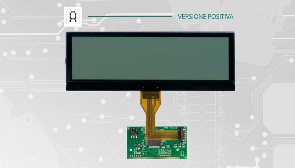
Back to product Seleziona lingua: Positive version SEPDISP29P Installation instructions for Citroën, DS, Fiat, Lancia, Peugeot, Toyota BORG – JOHNSON CONTROLS MFD display Before installing the new SEPDISP28P display, please read carefully the following instructions. Our technicians, for illustrative purposes only, have made a video tutorial about how to repair the module. DON’T SKIP ANY STEP. Watch the video tutorial Download the printable PDF WARNING: THIS PROCESS IS RECOMMENDED ONLY TO EXPERT AND QUALIFIED STAFF The display must be installed only with its related small PCB, as supplied in the original packaging; Before installing the new display SEPDISP29P, it is highly recommended to carefully read the following instructions and watch the video below. The video is for illustrative purpose only; Do not skip any steps. 1 Pic. 1 Pic. 2 De-solder the original display with a hot air de-soldering iron (Pic. 1). Clean with a solder wick and chisel tip to remove any excess tin (Pic. 2). A moderate amount of flux may be used to facilitate the cleaning process. Lastly, complete the cleaning with some solvent. 2 Position the small PCB leaving 1mm gap, as in picture 3, and solder each pin individually, one at the time, with 0,3mm thin solder wire and with conical tip at 350°C (Pic.4). In this case, using flux is not recommended to inexperienced staff as misusing it may damage the board irreversibly 3 With a flush cutter, cut off the central clip of the plastic base of the display and any other plastic part positioned by the new FPC, as it may damage it when re-assembling. 4 Peel off the rear protective film from the display. 5 Fit the display in its housing and re-attach the board on the rear. 6 With the aid of the tweezers, insert the FPC of the new display, with contacts facing down, into the connector on the small PCB. 7 Put back the module in the rear cover, making sure not to damage the FPC. Then, peel off the front film. 8 Lastly, re-attach the metal frame. 9 Switch on the module on a test bench using the Minitools CAN BUS generator SEP-RE-CAN008I, or directly on the vehicle. NOTE: If the display won’t turn on, please double check the soldering points. If the problem persists even after those checks, please send a picture of the small PCB soldered on the board at [email protected]. Minitools technicians will support you to complete the repair. Video Tutorial Repairing Citroën, Fiat, Lancia, Peugeot and Toyota defective multifunction unit with Minitools display SEPDISP29P