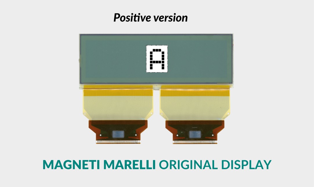
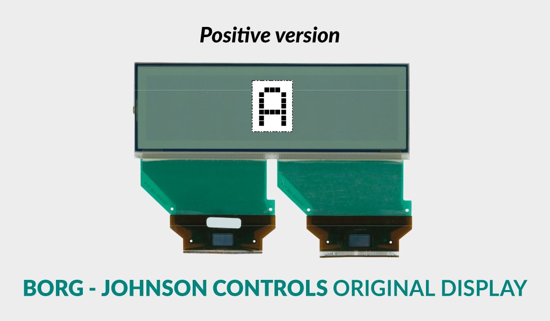
Positive version
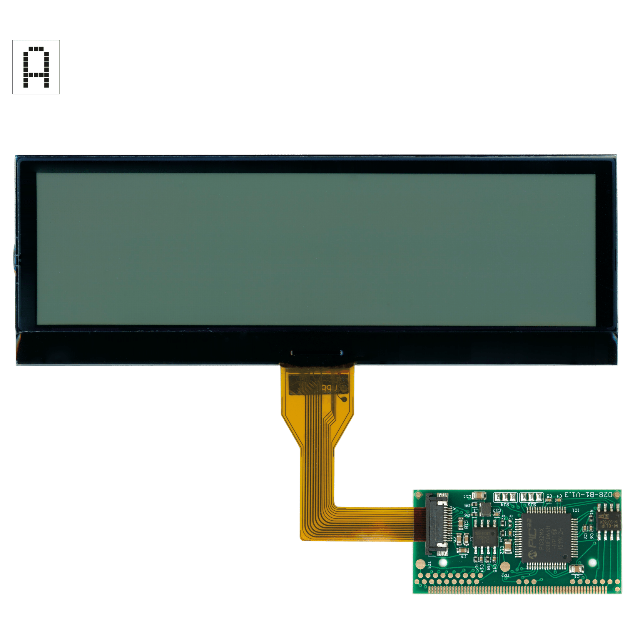
SEPDISP28P
Installation instructions for Citroën, DS, Fiat, Lancia, Peugeot, Toyota Magneti Marelli, Borg - Johnson Controls MFD display
Before installing the new SEPDISP28P display, please read carefully the following instructions. Our technicians, for illustrative purposes only, have made a video tutorial about how to repair the module.
DON’T SKIP ANY STEP.
WARNING: THIS PROCESS IS RECOMMENDED ONLY TO EXPERT AND QUALIFIED STAFF
- The display must be installed only with its related small PCB, as supplied in the original packaging;
- Before installing the new display SEPDISP28P, it is highly recommended to carefully read the following instructions
and watch the video below.
The video is for illustrative purpose only; - Do not skip any steps.
1
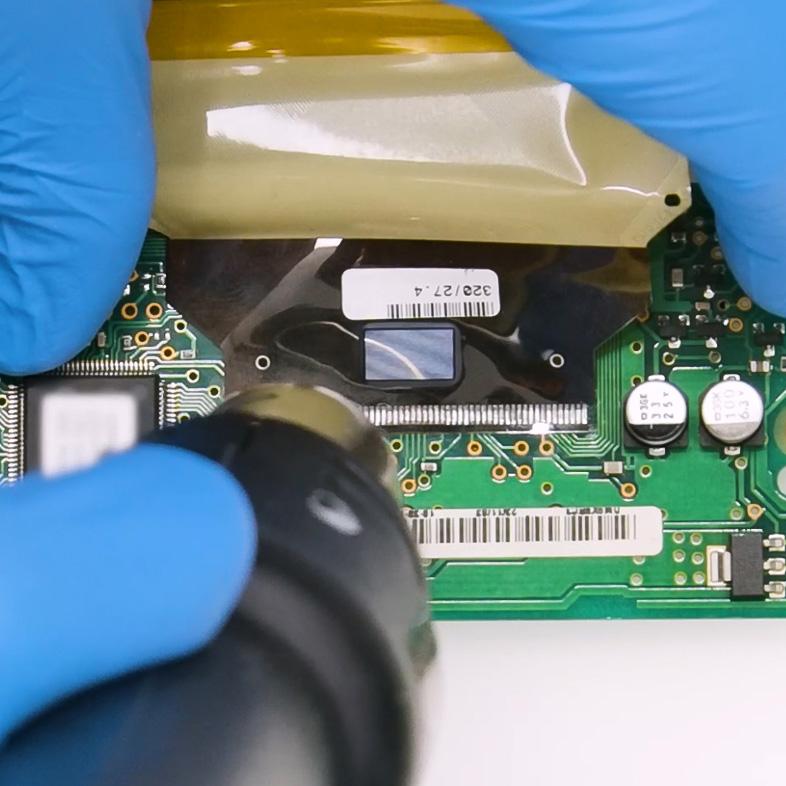

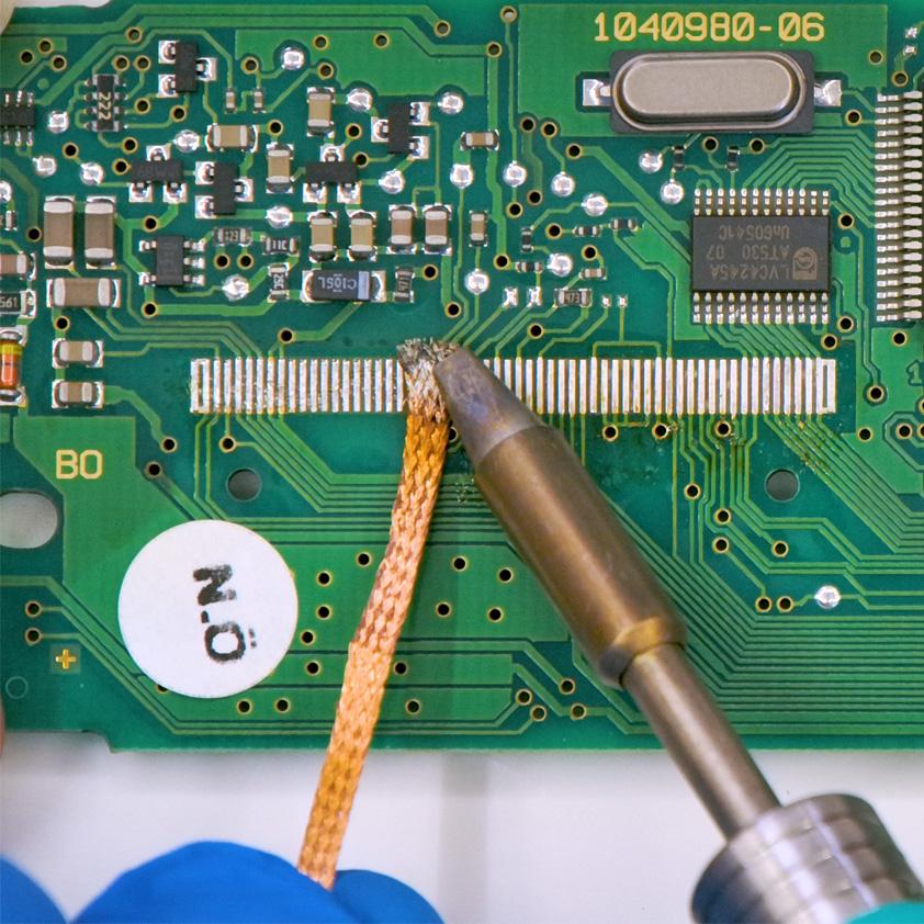
De-solder the original display with a hot air de-soldering iron (Pic. 1).
Clean with a solder wick to remove any excess tin (Pic. 2).
A moderate amount of flux may be used to facilitate the cleaning process.
Lastly, complete the cleaning with some solvent.
2

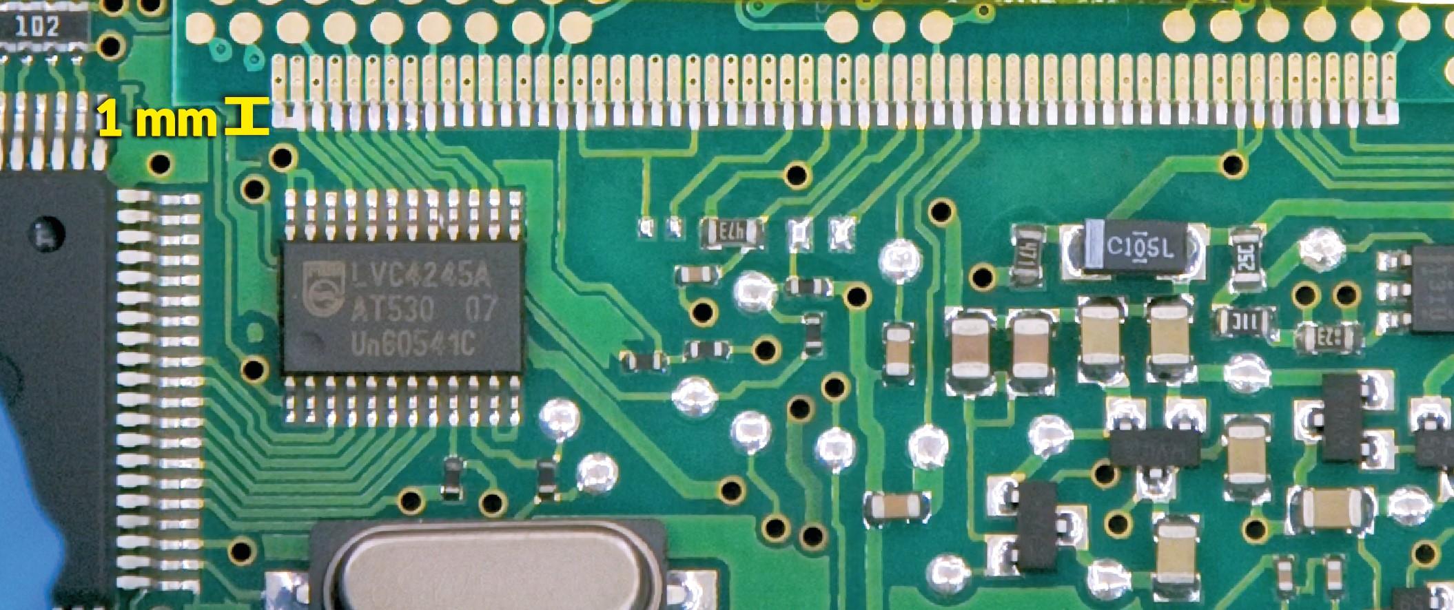
IMPORTANT: positioning the board with the connector on the left, place the small PCB of the new display on the right hand-side (Pic. 3).

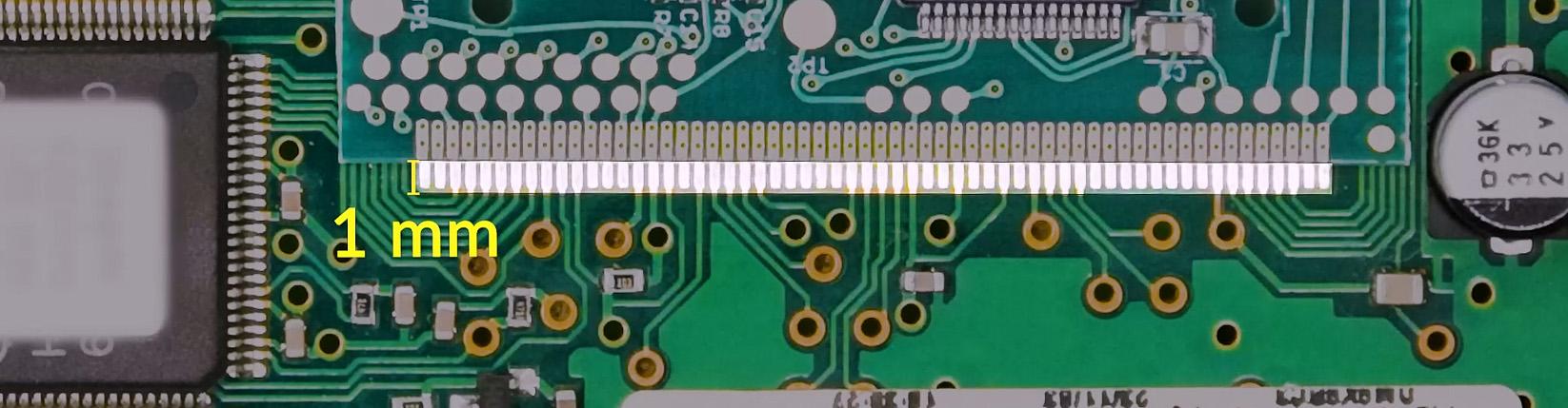
Position the small PCB leaving 1mm gap as in picture 4.
3

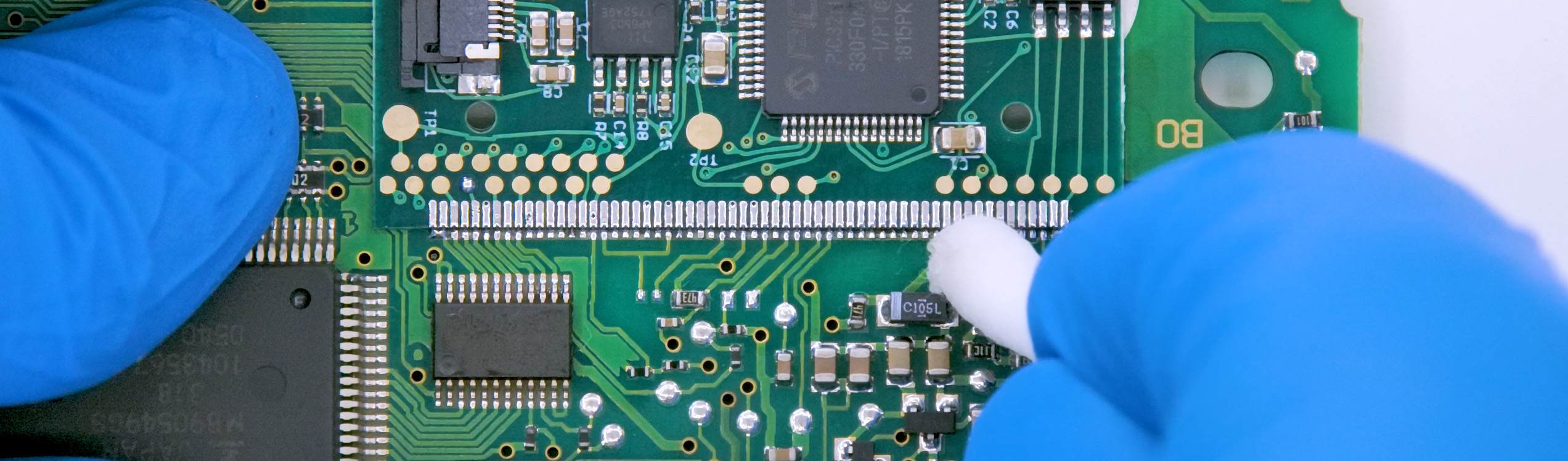
Solder each pin individually, one at the time, with 0,3mm thin solder wire and with conical tip at 350°C. In this case, using flux is not recommended to inexperienced staff as misusing it may damage the board irreversibly.

Once soldering is completed, clean with some solvent.
4
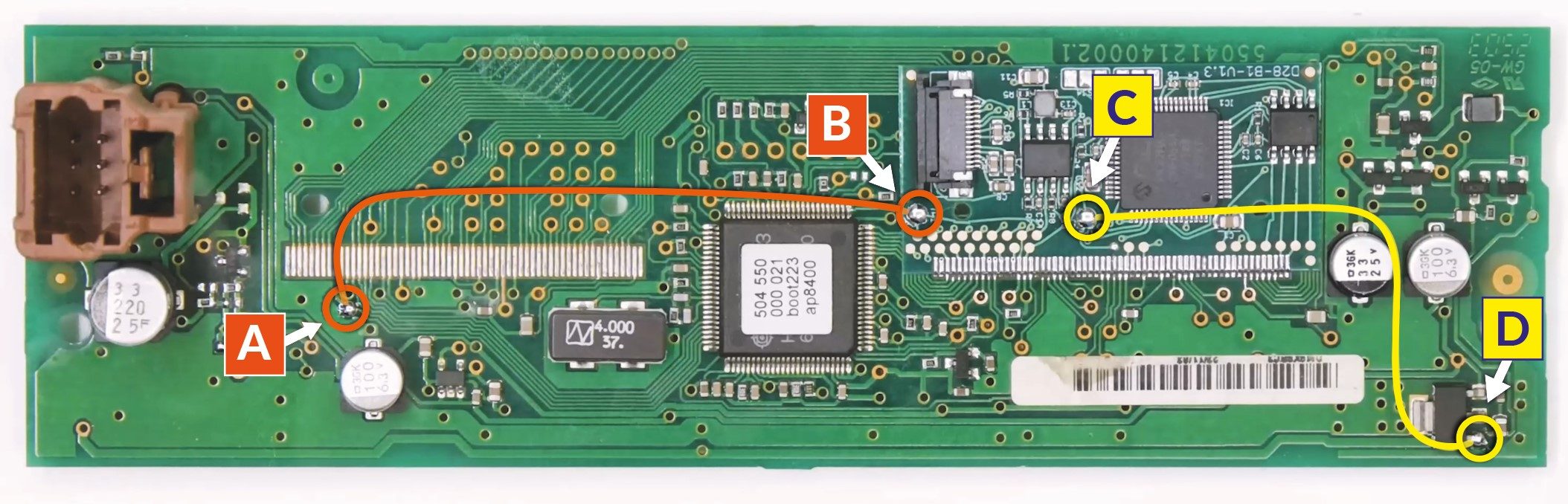
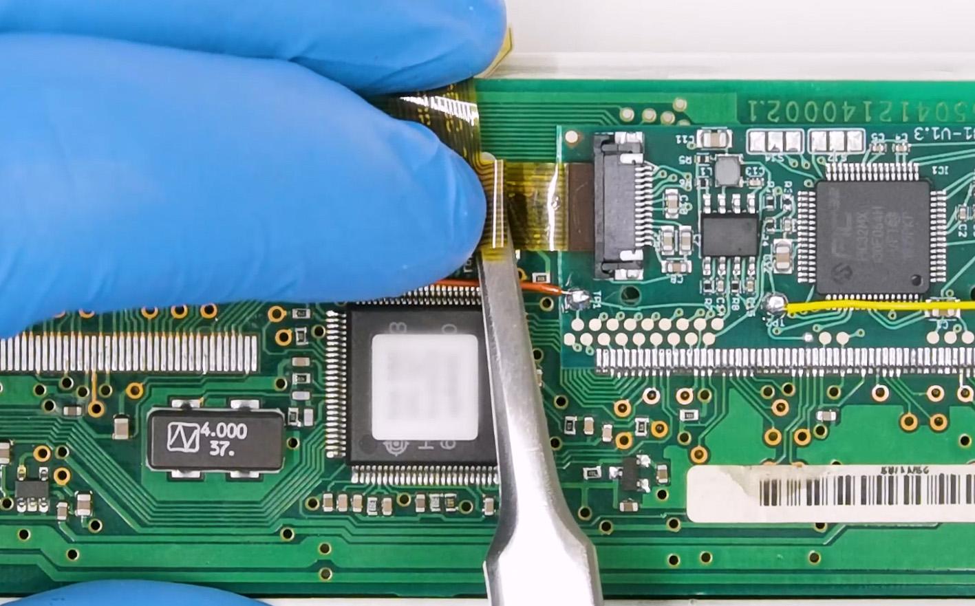
Solder 2 jumpers between the points A-B and C-D, as highlighted in
the picture above.
5

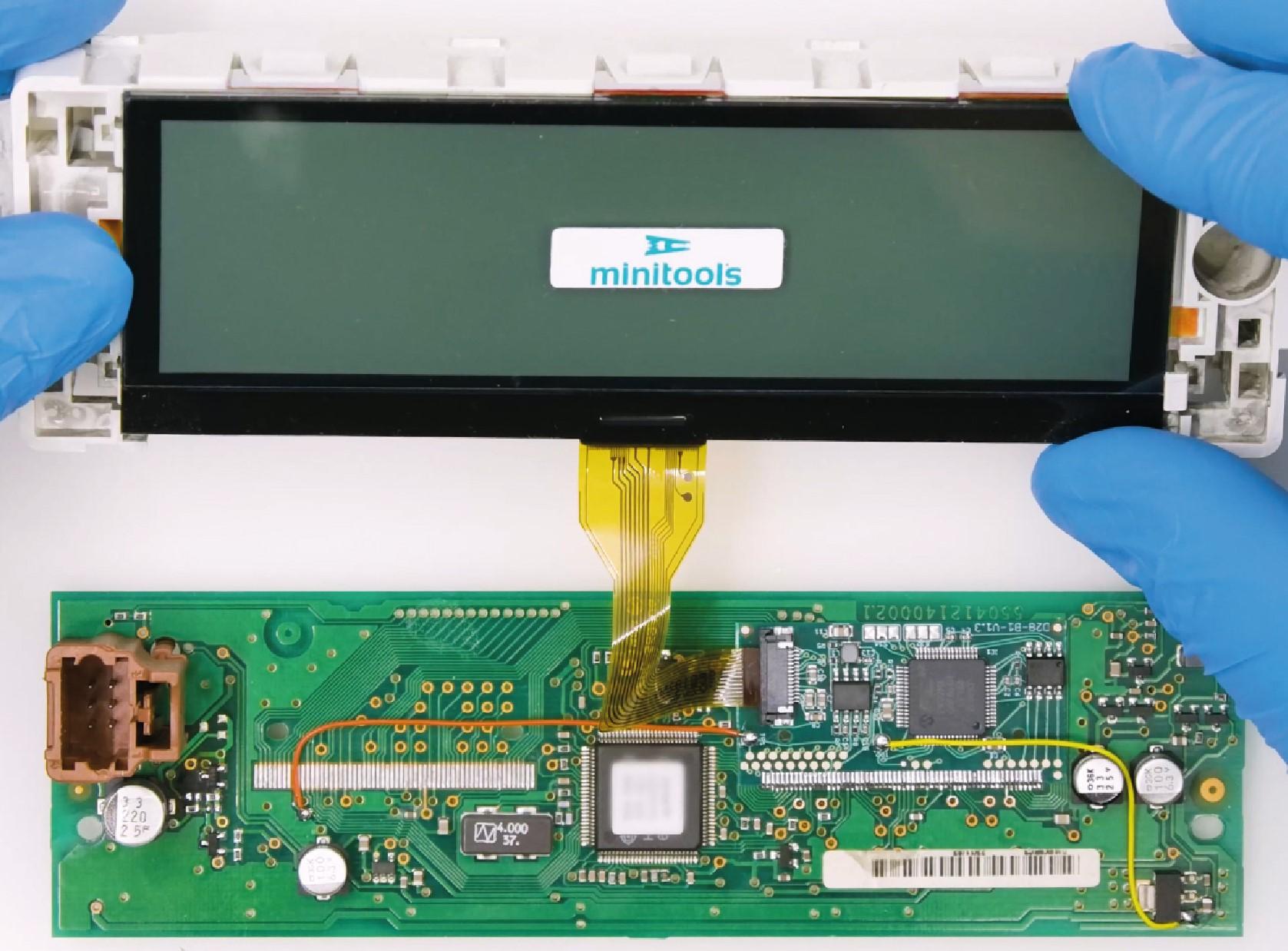
Insert the FPC of the new display, with contacts facing down, into the
connector of the small board.
6

With a flush cutter, cut off the central clip of the plastic base of the
display and any other plastic part positioned by the new FPC, as it may
damage it when re-assembling.
7
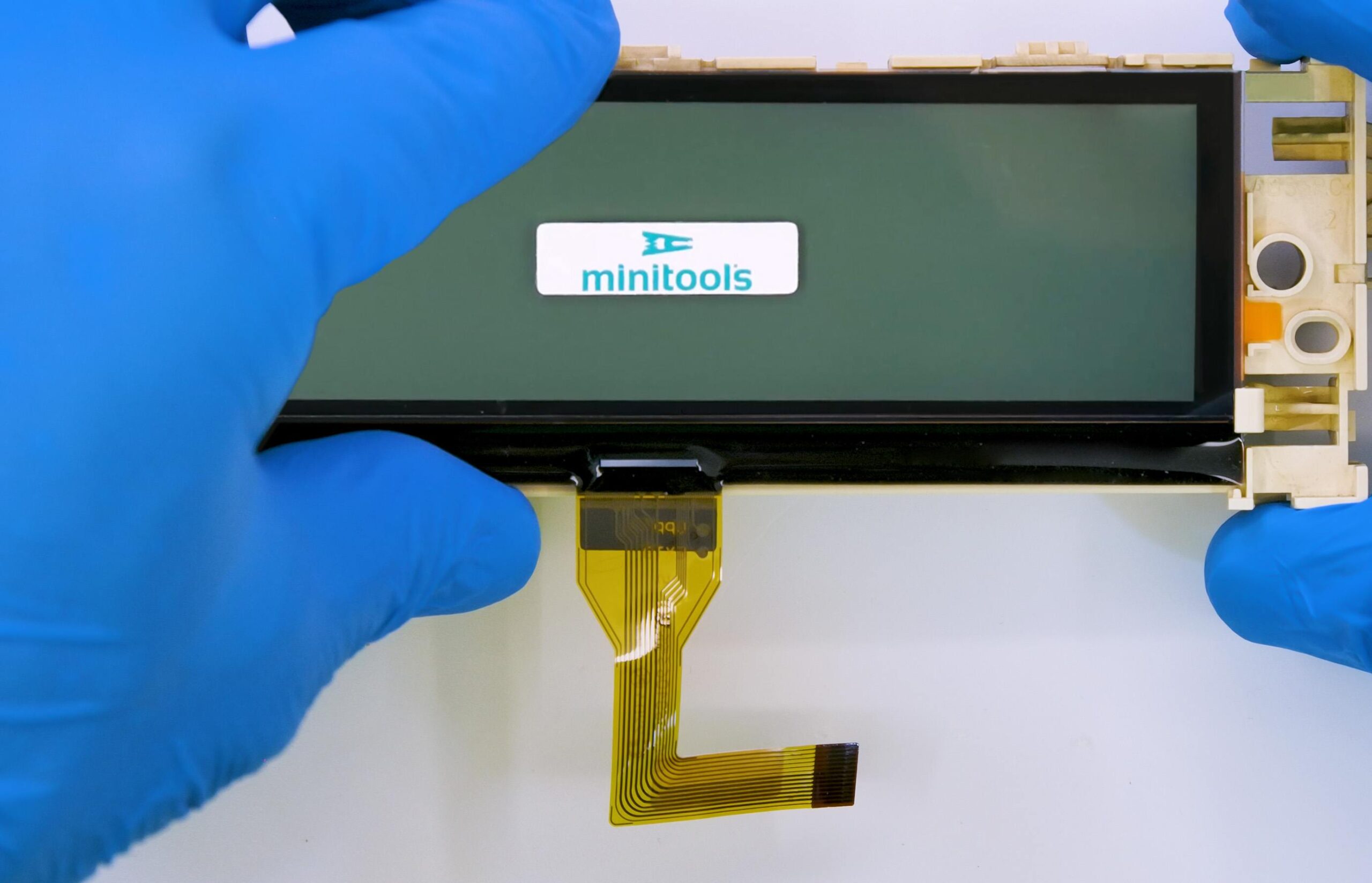
Peel off the rear protective film and fit the display on its base.
8

Re-attach the board.
9
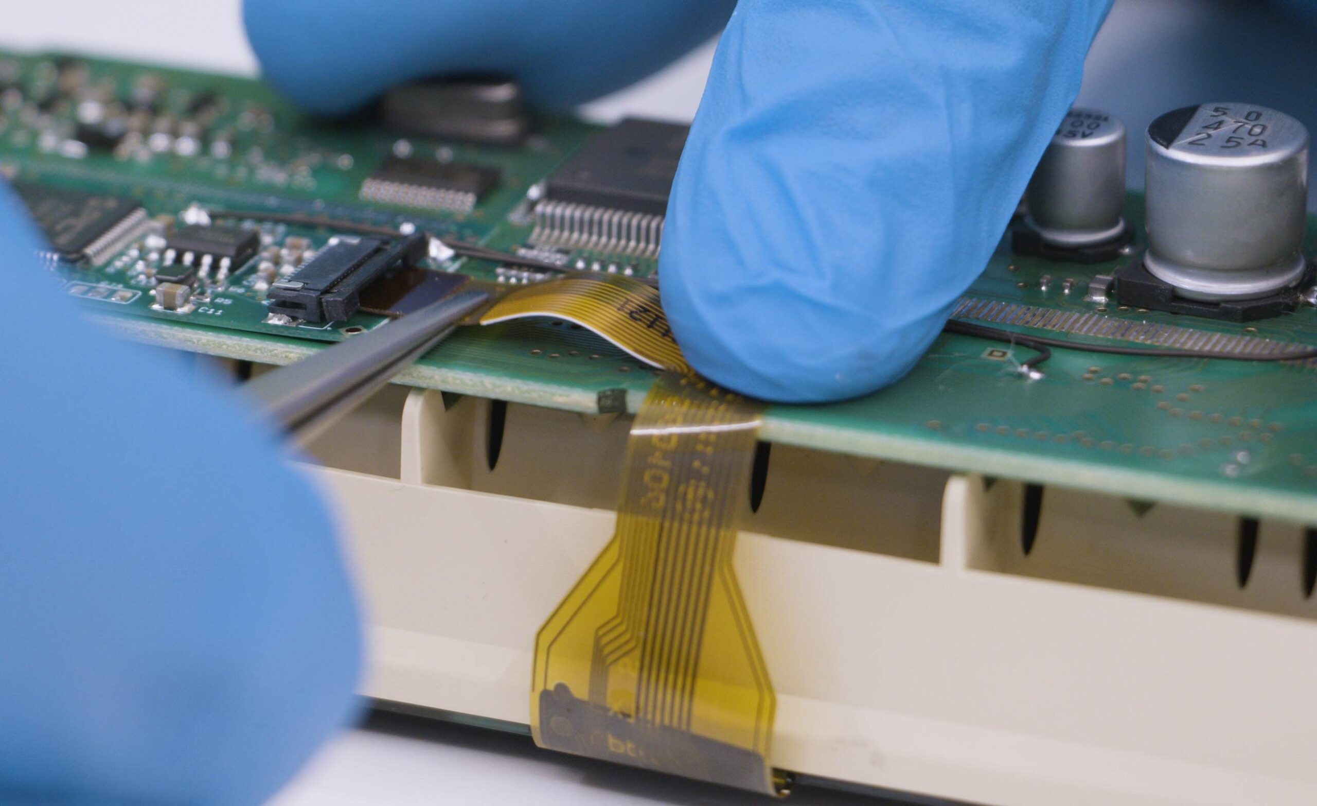
Carefully fold the FPC as shown in the picture.
10

Re-assemble the module, remove the protective film from the front side and switch it on as shown in the picture.
11
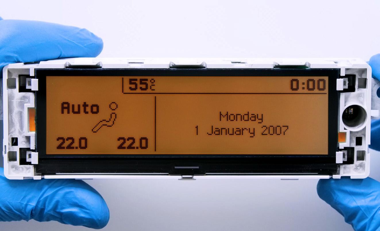
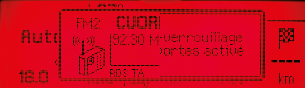
If the info are displayed clear and sharp as in the picture above, the problem is solved. Otherwise, see the section “PROBLEMS AND SOLUTIONS“.
NOTE: for some cars models, the colour of the module backlight may be
green.
Video Tutorial
How to repair Citroën, Fiat, Lancia, Peugeot and Toyota Magneti Marelli on-board computer with Minitools SEPDISP28P LCD display
1

De-solder the original display with a hot air de-soldering iron (Pic. 5).
Clean with a solder wick to remove any excess tin (Pic. 6). A moderate
amount of flux may be used to facilitate the cleaning process.
Lastly, complete the cleaning with some solvent.
2

IMPORTANT: Positioning the board with the connector on the left,
place the small PCB of the new display on the right hand-side (Pic. 7).
Position the small PCB leaving 1mm gap as in picture 8.
3

Solder each pin individually, one at the time, with 0,3mm thin solder wire andwith conical tip at 350°C. In this case, using flux is not recommended to inexperienced staff as misusing it may damage the board irreversibly.
Once soldering is completed, clean with some solvent.
4

Solder 2 jumpers between the points A-B and C-D, as highlighted in the picture above.
5

With a flush cutter, cut off the central clip of the plastic base of the
display and any other plastic part positioned by the new FPC, as it may
damage it when re-assembling.
6
Peel off the rear protective film and fit the display on its base.
7
Insert the FPC of the new display, with contacts facing down, into
the connector of the small board. Re-assemble the module making
sure not to damage the FPC and, lastly, peel off the front film of the
display.
8
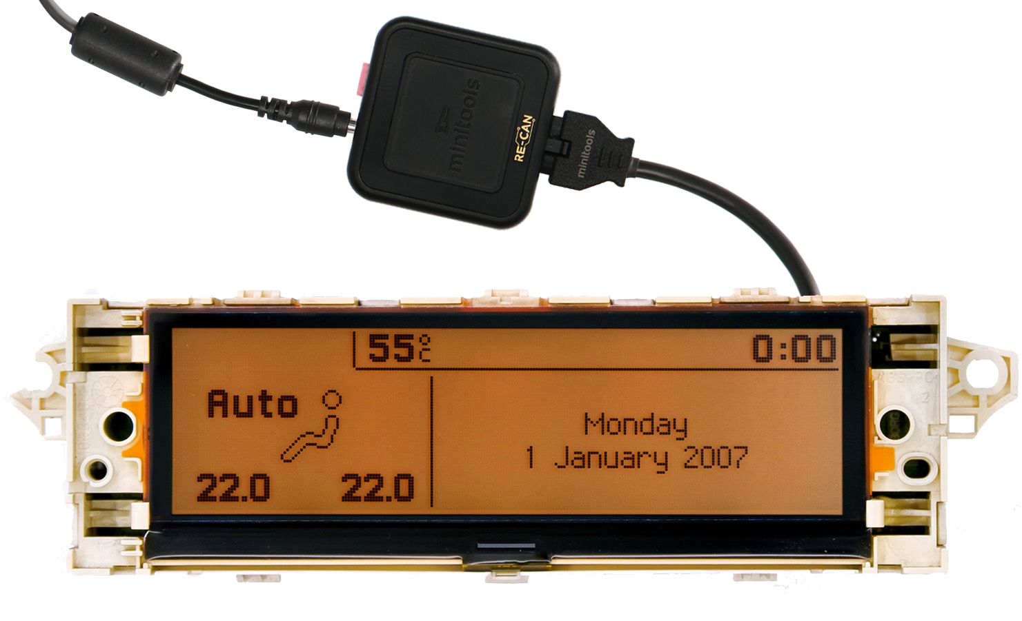
Switch on the module on a test bench using the Minitools CAN BUS generator SEP-RE-CAN00I.
If the info are displayed clear and sharp as in the picture above, the problem is solved.
Otherwise, see the section “PROBLEMS AND SOLUTIONS” beside.
PROBLEMS AND SOLUTIONS
(FOR MAGNETI MARELLI and BORG - JOHNSON CONTROLS)
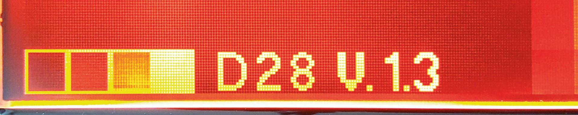
If a screen as in picture 9 should appear on the display, the solderings of the small PCB may have been done wrongly; please double check them.
On some car models, after switching on the module, some info may appear incomplete or overlapped as in picture 10. In this case, jumper the pads with some solder as in picture 11.

NOTE:
Once the module has been switched on, if the display doesn’t show any information, please double check the soldering points. If the problem persists even after those checks, please send a picture of the small PCB soldered on
the board at [email protected]. Minitools technicians will support you to complete the repair.