
SEPDISP43V3
Installation instructions
Before installing the new SEPDISP43V3 display, please read the following instructions carefully.
DO NOT SKIP ANY STEPS.
1


LCD display kit 88×64 pixel + PCB, adaptable to the following BIF/dashboards/hour meter John Deere:
– 5000 Series – 6000 Series
– 6010 Series – 6020 Series
– 6030 Series – 7020 Series
The SEPDISP43V3 kit consists of a PCB to be soldered to the dashboard motherboard and an LCD display with FPC (to be fitted into the PCB connector provided).
2
Warning
– The display must be installed only with the PCB supplied in the original packaging;
– Before installing the new display SEPDISP43V3, please read the following instructions carefully and watch the video tutorial. This video does not specifically refer to SEPDISP43V3, but it shows the techniques used for assembly;
– Do not skip any step.
3

After desoldering the original display, clean the contacts with a desoldering braid to remove excess solder to prevent the PCB from being lifted. Flux can be used.
4


Place the PCB on the instrument cluster main board leaving 1 mm gap.
5


Solder each pin, one at a time, with 0.3 mm tin solder wire and needle tip. Don’t use flux. After soldering the PCB, clean with a suitable solvent.
6

Insert the FPC of the new display from the slot in the instrument cluster motherboard.
7
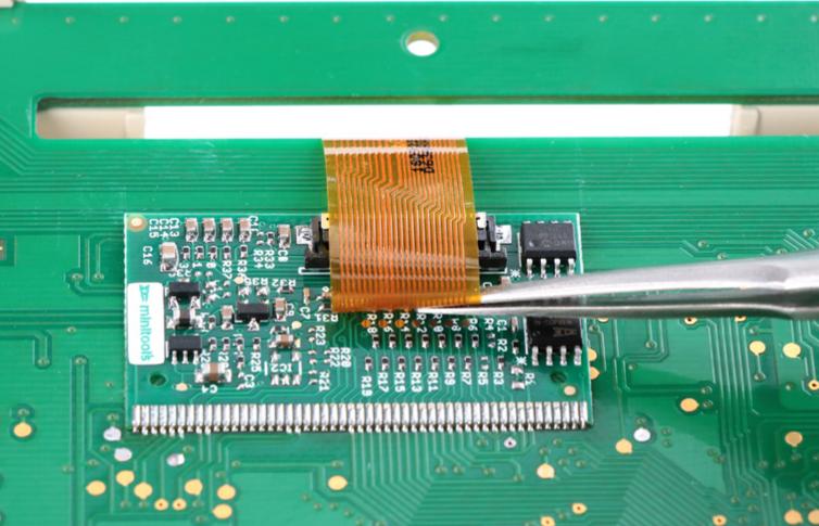
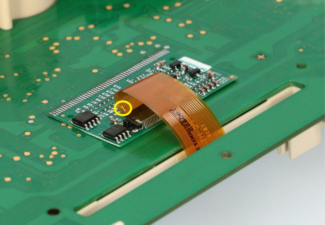
Rotate the FPC in order to insert it in the PCB connector, keeping pin 1 as shown in the picture.