SEPDISP06: Modification for Mercedes C-Class W203 and G-Class W463 display
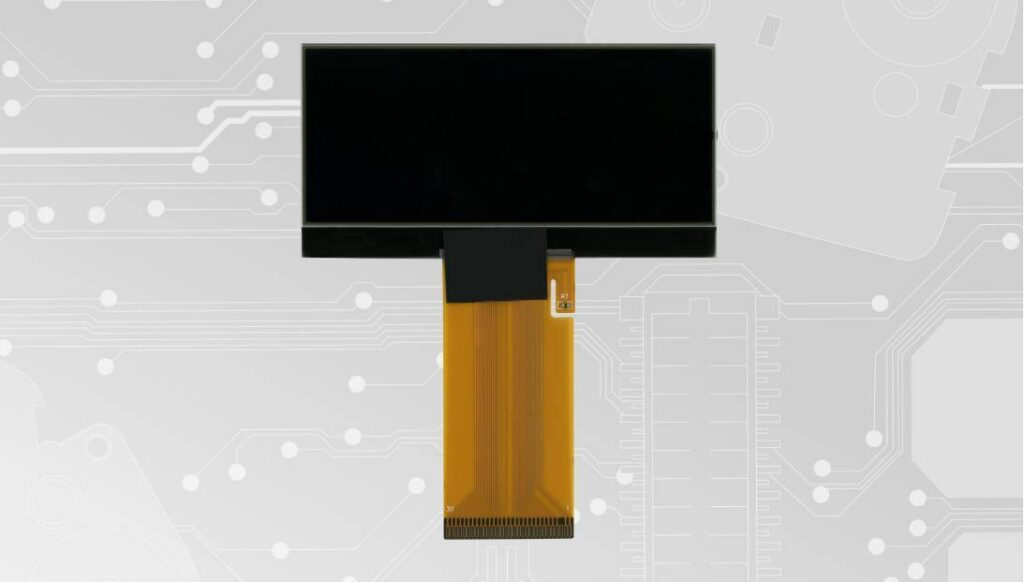
Back to product Seleziona lingua: SEPDISP06 Modification for Mercedes C-Class W203 and G-Class W463 LCD display Before installing the new SEPDISP06 display, please read the following instructions carefully. For illustrative purposes, our technicians have produced a video tutorial on how to carry out the odometer repair.DO NOT SKIP ANY STEPS. Watch the video tutorial Download printable PDF ATTENTION: THESE OPERATIONS ARE ONLY RECOMMENDED FOR EXPERIENCED PERSONNEL. The following modification is necessary for the correct functioning of SEPDISP06 display. Replace the display in an ambient temperature of 25 °C. After replacing the LCD, switch on the cluster with the Minitools connector SEP-PA011. Identify the PCB of your dashboard (PCB1 or PCB2) and measure the voltage between A and B points. Pic. 1 Pic. 2 If the voltage measured is between 7.7V and 7.8V, no modification is necessary; If the voltage detected is instead lower than 7.7V or higher than 7.8V, it is necessary to do the modification described in thefollowing paragraph “EEPROM MODIFICATION“. EEPROM MODIFICATION NOTE: For this modification, it is necessaryto use an EEPROM programmer.We recommend our SEP-EECLIP. De-solder the 93C86 EEPROM from thePCB; Set the programmer reading in hexadecimal (HEX); ATTENTION: make a backup of the EEPROM,before the modification. To reach a voltage between 7.7V and 7.8V identify the 01E4, 01E5, 01E6 and 01E7 locations and modify their values: increasing or decreasing the 4 locations values by 1 HEX unit, the variation will be +/- 0.09 V. If not familiar with hexadecimal calculation, it ispossibile to use the calculation tool in the boxbeside, simply typing in the values. Once these operations have been done, solder back the 93C86 EEPROM on the PCB, switch on the instrument cluster and check again the tension between points A and B.Verify, then, if a voltage between 7.7V and 7.8V has actually been reached. If not, decrease or increase the values of the locations until the voltage is between that range. WARNING: if the VOLTAGE HAS NOT CHANGED after the EEPROM modification, see the following page “PROBLEMS AND SOLUTIONS”. PROBLEMS AND SOLUTIONS Pic. 1 If you’ve done the modification on an instrument cluster with the “PCB1” and the voltage has NOT changed, please CONTACT US by e-mail at [email protected]. Pic. 2 If you’ve done the modification on an instrument cluster with the “PCB2” instead, and the voltage has NOT changed FOLLOW THE INSTRUCTIONS shown in the following paragraph “EEPROM MODIFICATION”. Eeprom modification De-solder again the 93C86 EEPROM fromthe PCB; Set the programmer reading in hexadecimal (HEX); ATTENTION: upload the backup previouslymade on the EEPROM, to restore the originaldata. To reach a voltage between 7.7V and 7.8V, identify the location 03B3 and modify its value: decreasing the location value by 1 HEX unit, the variation will be + 0.0125V (or vice versa). If not familiar with hexadecimal calculation, it is possibile to use the calculation tool in the box beside, simply typing in the values. Once these operations have been done, solder back the 93C86 EEPROM on the PCB, switch on the instrument cluster and check again the tension between points A and B. Verify, then, if a voltage between 7.7V and 7.8V has actually been reached. If not, decrease or increase the value of the location until the voltage is between that range. WARNING: if the VOLTAGE HAS NOT CHANGED at all after the EEPROM modification, CONTACT US. Video Tutorial How to repair Mercedes C-Class W203 and G-Class W463 dashboards with Minitools SEPDISP06 LCD screen