CALCULATION OF THE NEW VALUES OF THE LOCATIONS
01BF LOCATION
01CF LOCATION
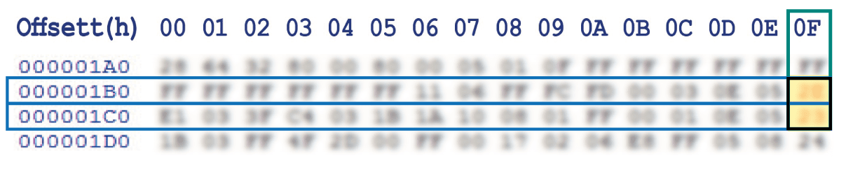
*How to identify 01BF and 01CF locations values on the EEPROM
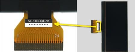
Before installing the new SEPDISP08-7V display, please read carefully the following instructions. Our technicians, for illustrative purposes only, have made a video tutorial about how to repair the instrument panel.
DON’T SKIP ANY STEP.
THE FOLLOWING MODIFICATION IS NECESSARY FOR THE CORRECT FUNCTIONING OF SEPDISP08-7V DISPLAY.
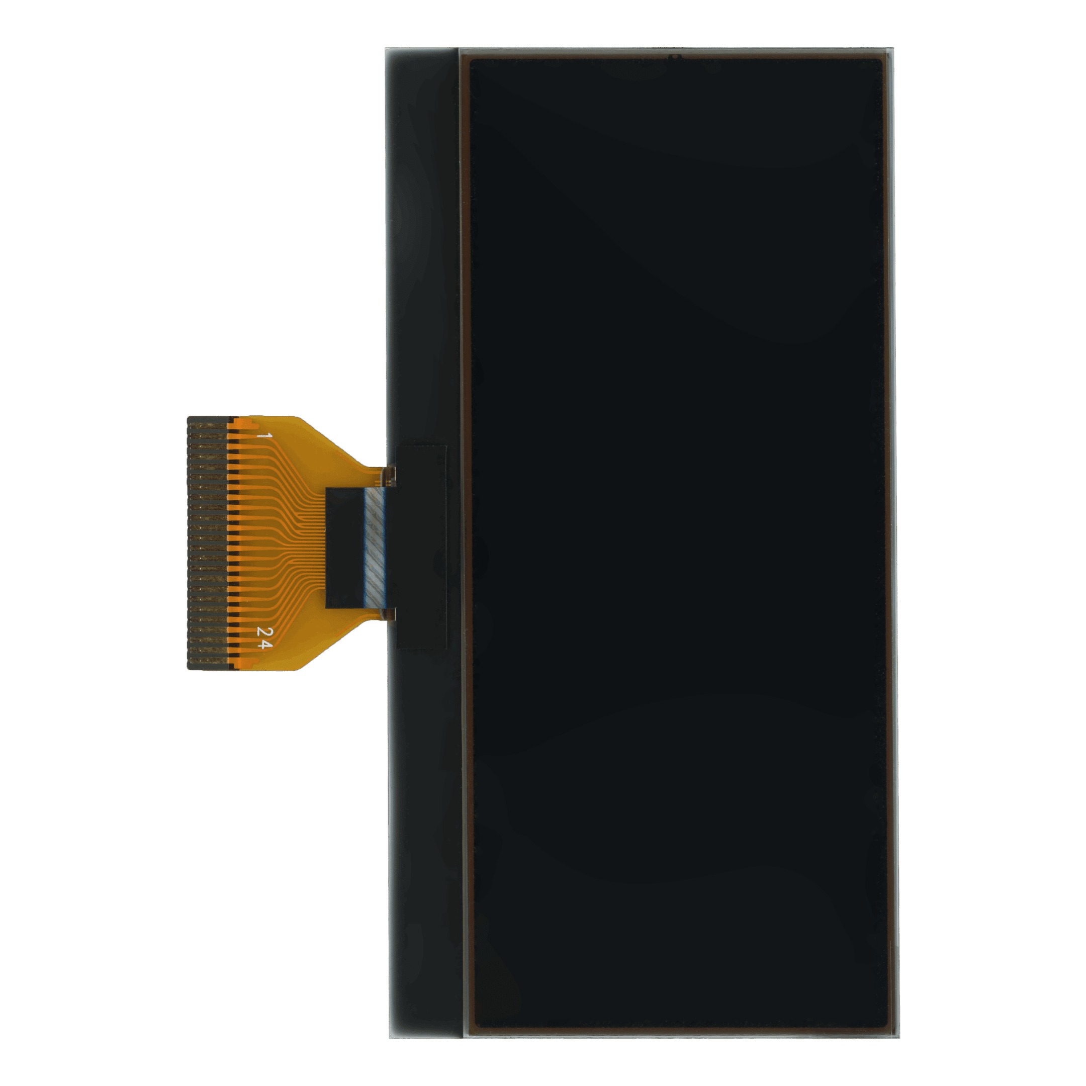
• Replace the display in an ambient temperature of 25 °C.
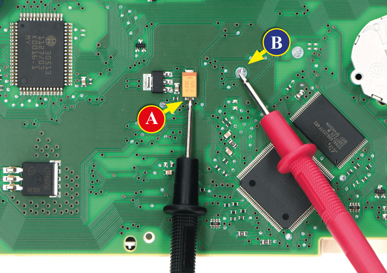
• After replacing the LCD, switch on the cluster (pin no. 1 negative, pin no. 5 and no. 6 positive) and measure the voltage between A and B points as in picture 1.
• If the voltage measured is between 6.45V and 6.55V no modification is necessary;
• If the voltage detected is instead lower than 6.45V or higher than 6.55V, it is necessary to do the modification described in the following paragraph “EEPROM MODIFICATION“.
NOTE: For this modification, it is necessary to use an EEPROM programmer.
We recommend our SEP-EECLIP.
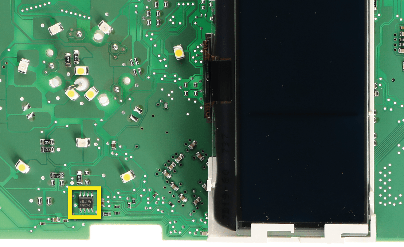
• De-solder the EEPROM (24C04 or 24C32), highlighted in picture 2, located on the PCB.
• First, set the programmer reading in 8 bit hexadecimal (HEX).
• ATTENTION: Make a backup of the EEPROM, before the modification.
• To reach a voltage between 6.45V and 6.55V, identify the 01BF and 01CF locations and modify their values: increasing or decreasing the 2 values by 1 HEX unit, the variation will be +/- 0.09V.
If not familiar with hexadecimal calculation, it is possible to use the calculation tool in the box beside, simply typing in the values.
NOTE: For the version that can be used offline download the PDF.
Once these operations have been done, solder back the EEPROM on the PCB,
switch on the instrument cluster and check again the tension between points A and B (see picture 1).
Verify, then, if a voltage between 6.45V and 6.55V has actually been reached. If not, decrease or increase the values of the locations until the voltage is between that range.
THE FOLLOWING MODIFICATION IS NECESSARY FOR THE CORRECT FUNCTIONING OF SEPDISP08-7V DISPLAY.
• Replace the display in an ambient temperature of 25 °C.
• After replacing the LCD, switch on the cluster (pin no. 1 negative, pin no. 5 and no. 6 positive) and measure the voltage between A and B points as in picture 1.
• If the voltage measured is between 6.95V and 7.05V no modification is necessary;
• If the voltage detected is instead lower than 6.95V or higher than 7.05V, it is necessary to do the modification described in the following paragraph “EEPROM MODIFICATION“.
Once these operations have been done, solder back the EEPROM on the PCB,
switch on the instrument cluster and check again the tension between points A and B (see picture 1).
Verify, then, if a voltage between 6.95V and 7.05V has actually been reached. If not, decrease or increase the values of the locations until the voltage is between that range.