*How to identify the locations 001D and 0027 on the EEPROM
• Replace the display in an ambient temperature of 25 °C.
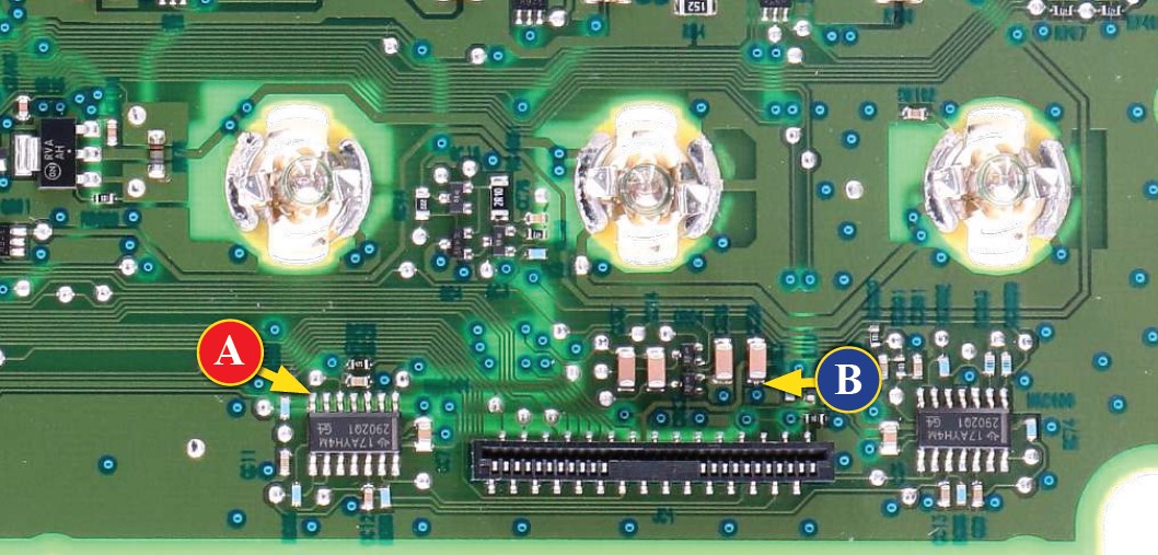
• After replacing the LCD, switch on the cluster on a test bench with the CAN-BUS generator SEP-CAN-MODUS to measure the voltage between the points A and B (see picture 1). Alternatively, it is possible to switch on the module directly on the car, but this second option is not recommended.
• If the voltage measured is between 8,10V and 8,30V no modification is needed;
• If the voltage is, instead, lower than 8.10V or higher than 8,30V the modification is necessary. The operations to
carry out are explained in the following paragraph “EEPROM MODIFICATION“, and distinguished according to the
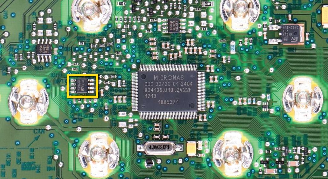
code of EEPROM on the PCB (see picture 2), the 93C66 or the 93C56.
NOTE: For this modification, it is necessary to use an EEPROM programmer.
We recommend our SEP-EECLIP.
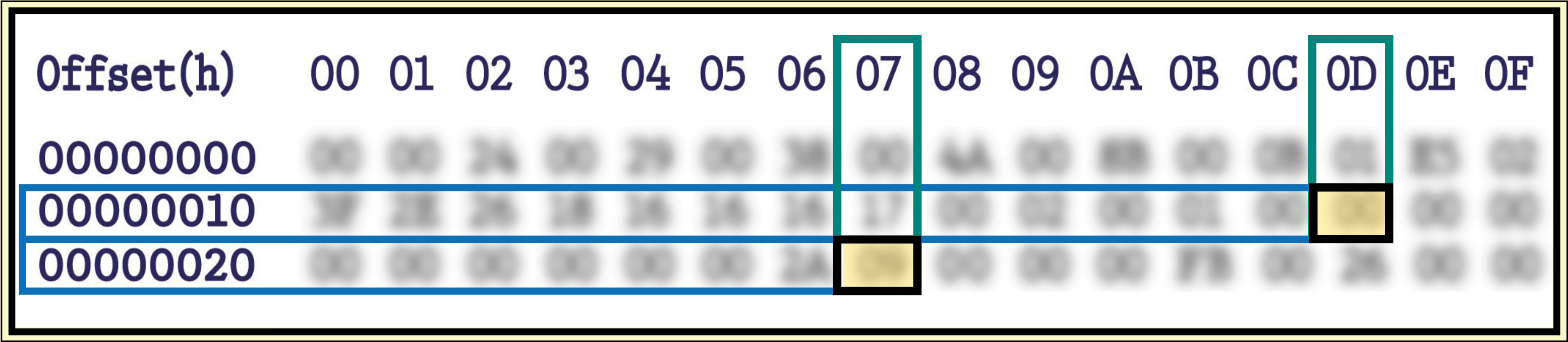
• De-solder the EEPROM 93C66 highlighted in picture 2,
located on the PCB;
• First, set the programmer reading in hexadecimal (HEX);
ATTENTION: Make a backup of the EEPROM, before
the modification.
• To reach a voltage between 8,10V and 8,30V, identify the locations 001D and 0027 and modify their values: increasing or decreasing the values by 1 HEX unit, the variation will be +/- 0.09V.
If not familiar with hexadecimal calculation, it is possible to use the calculation tool in the box below, simply typing in the values.
NOTE: For the version that can be used offline, download the PDF.
VERIFICATION
Once these operations have been done, save the file just modified and upload it on the EEPROM. Solder back the 93C66 EEPROM on the PCB, switch on the instrument cluster and check again the tension between points A and B (see picture 1).
Verify, then, if a voltage between 8,10V and 8,30V has actually been reached.
If not, decrease or increase the values of the locations until the voltage is between that range.
NOTE: For this modification, it is necessary to use an EEPROM programmer.
We recommend our SEP-EECLIP.
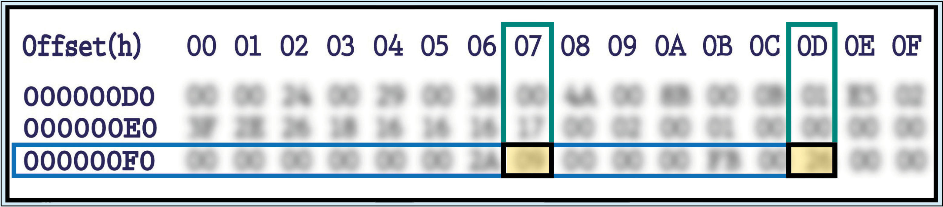
• De-solder the EEPROM 93C56 highlighted in picture 2,
located on the PCB;
• First, set the programmer reading in hexadecimal (HEX);
ATTENTION: Make a backup of the EEPROM, before
the modification.
• To reach a voltage between 8,10V and 8,30V, identify the locations 00F7 and 00FD and modify their values: increasing or decreasing the values by 1 HEX unit, the variation will be +/- 0.09V.
If not familiar with hexadecimal calculation, it is possible to use the calculation tool in the box below, simply typing in the values.
NOTE: For the version that can be used offline, download the PDF.
VERIFICATION
Once these operations have been done, save the file just modified and upload it on the EEPROM. Solder back the 93C56 EEPROM on the PCB, switch on the instrument cluster and check again the tension between points A and B (see picture 1).
Verify, then, if a voltage between 8,10V and 8,30V has actually been reached.
If not, decrease or increase the values of the locations until the voltage is between that range.