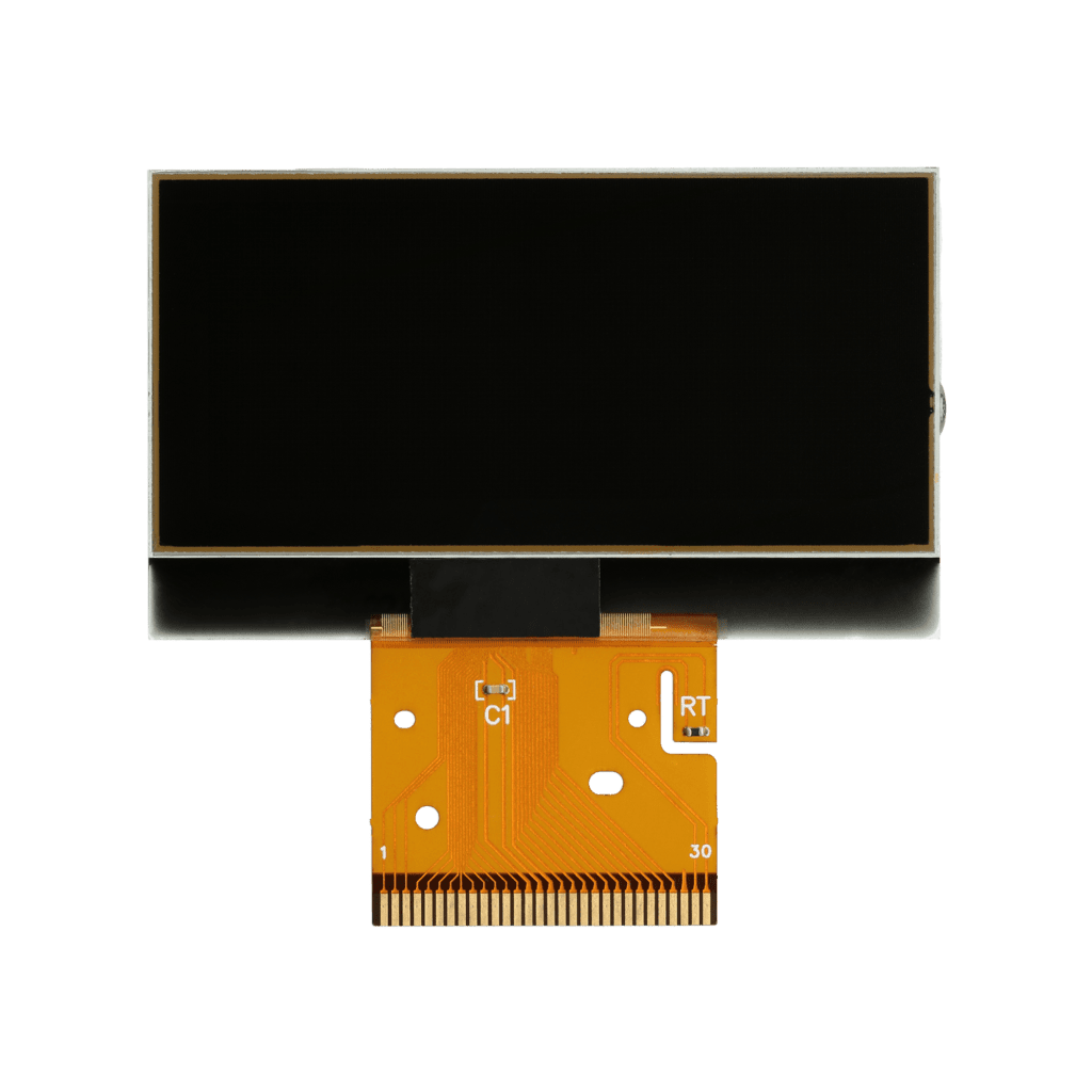
Modification for Mercedes SL R230 and SLR McLaren LCD display
WARNING: This process is recommended only to expert and qualified staff.
Before installing the new SEPDISP71 display, please read the following instructions carefully. For illustration purposes, our technicians have made a video tutorial on how to do the repair.
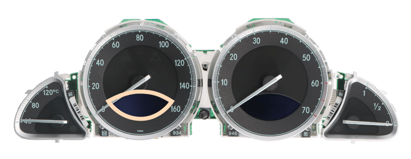
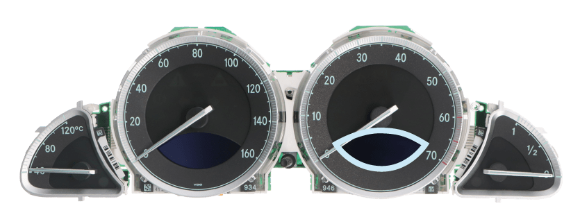
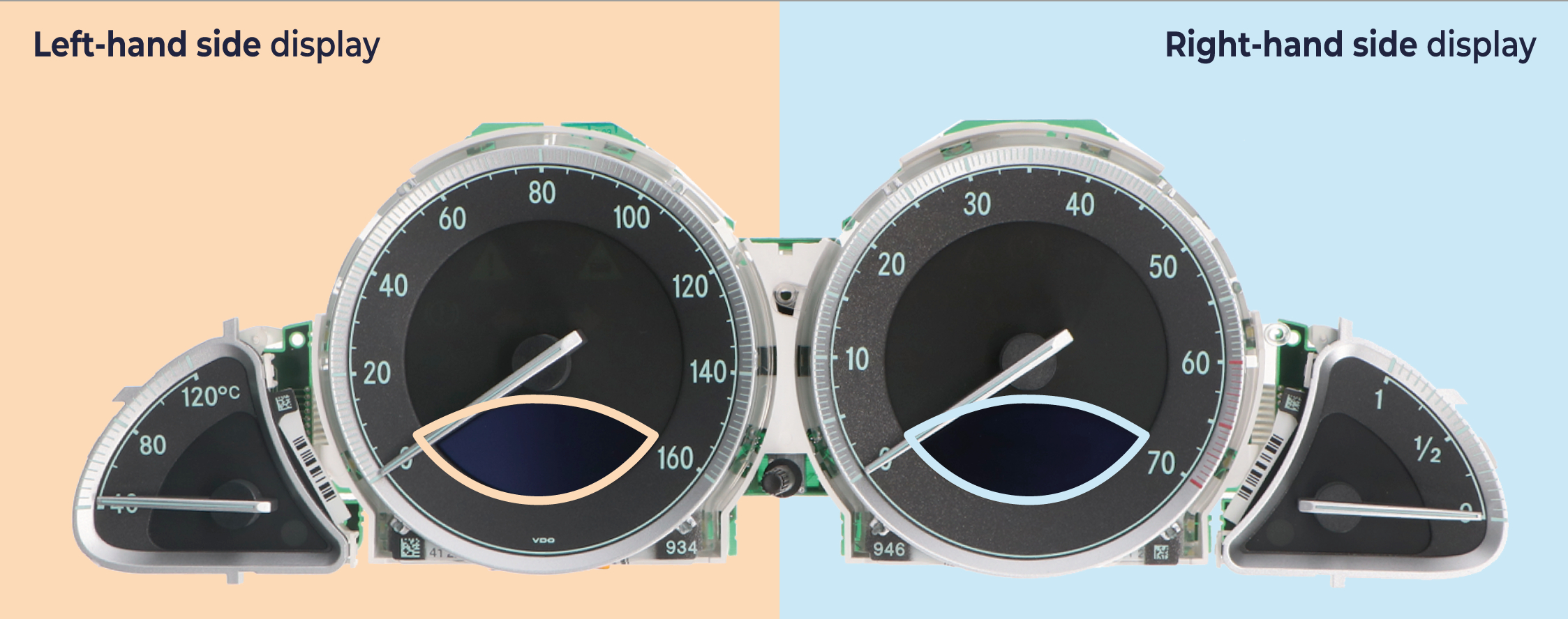
THE FOLLOWING MODIFICATION IS NECESSARY FOR THE CORRECT FUNCTIONING OF SEPDISP71 DISPLAY.SEPDISP71 CAN REPLACE BOTH SCREENS OF THE INSTRUMENT CLUSTER (see picture 1).
Replace the display in an ambient temperature of 25 °C.
Picture 1
EEPROM identification:
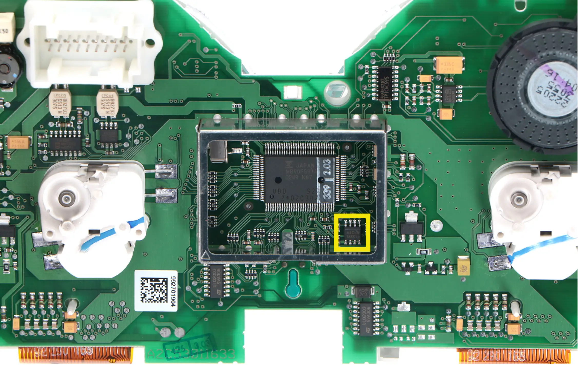
Remove the metal shielding on the rear side of the PCB and identify the EEPROM inside (see picture 2).
‣ If the EEPROM is marked “93C86” click here;
‣ If the EEPROM is marked “24C16”, click here.
Picture 2
Steps for EEPROM 93C86
To adjust SEPDISP71 screen / screens voltage:
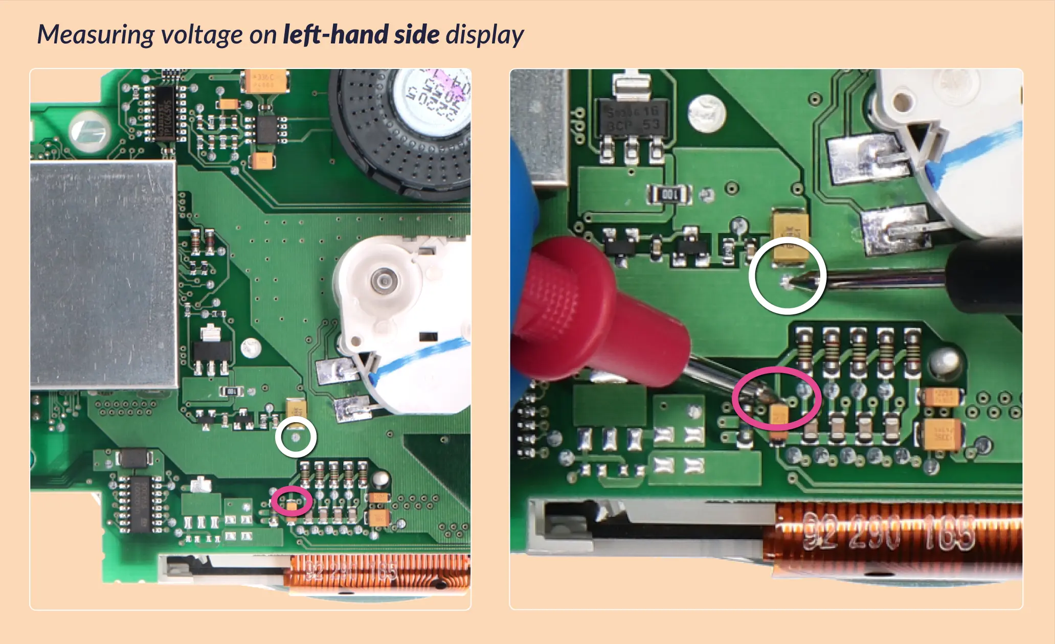
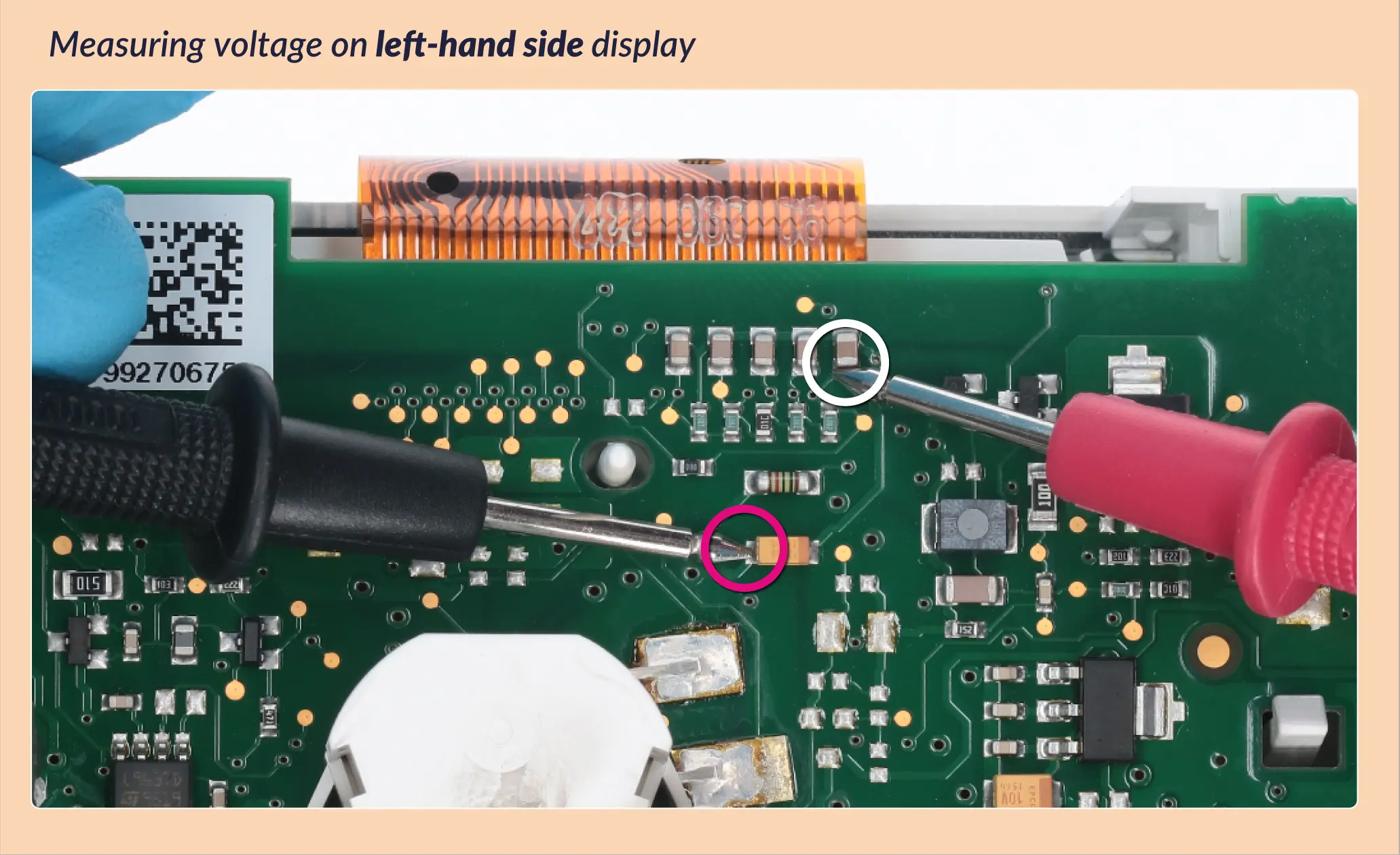
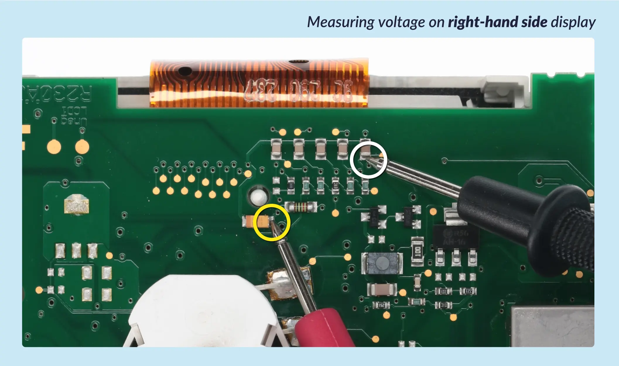
‣ Switch on the clusterwith the Minitools connector SEP-PA011. ‣ For the LEFT-HAND SIDE display, measure the voltage between the points indicated in picture 3 ; for the RIGHT-HAND SIDE display measure between those indicated in picture 4. – If the voltage measured is between 7,25V and 7,35V, no modification is necessary; – If the voltage is instead lower than 7,25V or higher than 7,35V, it is necessary to do the modification described in the following paragraph “EEPROM 93C86 MODIFICATION”.
Picture 3
Picture 4
EEPROM 93C86 modification
ATTENTION: For this modification it is necessary to use an EEPROM programmer. We recommend our SEP-EECLIP.
PROCEDURES:
• First, set the programmer reading in 8 bit hexadecimal (HEX). • Desolder and make a backup of the EEPROM 93C86 (shown in picture 2), which is located inside the metal enclosure on the back of the cluster. •To reach a voltage close to 7.30V:
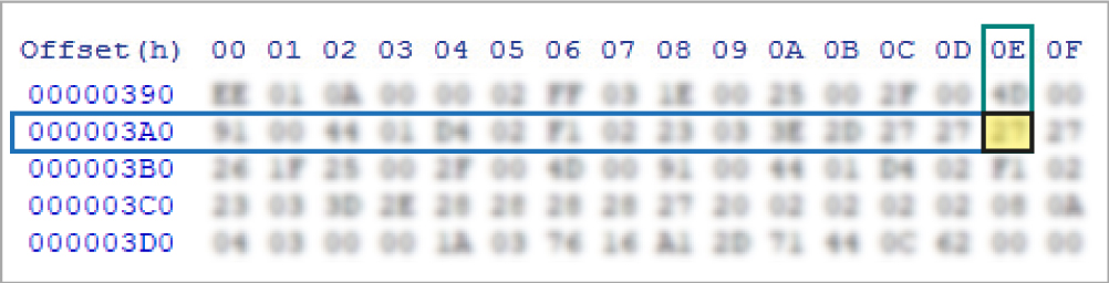
– act on the location 03AE for the left-hand side display
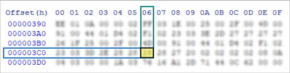
– act on the location 03C6 for the right-hand side display
Please note that increasing these locations by 1 HEX unit, the variation will be + 0,07 V or vice versa.
NOTE: If not familiar with hexadecimal calculation, it is possible to use the calculation tool in the box below, simply typing in the values.
SEPDISP71 - EEPROM 93C86
Calculation of the new values of the locations
Left-hand side display
Right-hand side display
* How to identify the locations 03AE and 03C6 values on the EEPROM programmer
Once these modifications have been done, measure again the voltage between the points indicated in picture 3 and 4 and check that it actually is between 7.25V and 7.35V, if not, increase or decrease the locations until the value is as close as possible to
7.30V.
Steps for EEPROM 24C16
To adjust SEPDISP71 screen / screens voltage:
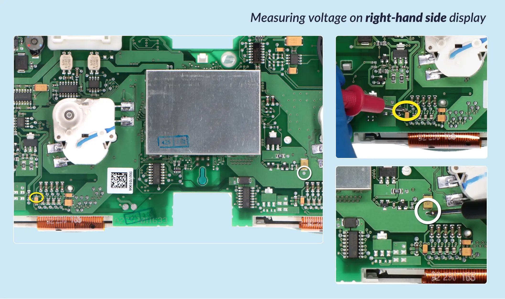
‣ Switch on the cluster with the Minitools connector SEP-PA011. ‣ For the LEFT-HAND SIDE display, measure the voltage between the points indicated in picture 5 ; for the RIGHT-HAND SIDE display measure between those indicated in picture 6. – If the voltage measured is between 7,29V and 7,31V, no modification is necessary; – If the voltage is instead lower than 7,29V or higher than 7,31V, it is necessary to do the modification described in the following paragraph “EEPROM 24C16 MODIFICATION”.
Picture 5
Picture 6
Eeprom 24C16 modification
ATTENTION: For this modification it is necessary to use an EEPROM programmer. We recommend our SEP-EECLIP.
PROCEDURES:
• First, set the programmer reading in 8 bit hexadecimal (HEX). • Desolder and make a backup of the EEPROM 24C16 (shown in picture 2), which is located inside the metal enclosure on the back of the cluster. • To reach a voltage close to 7.30V:
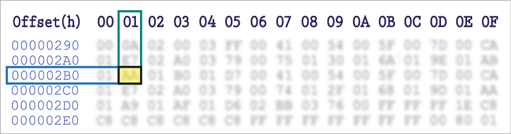
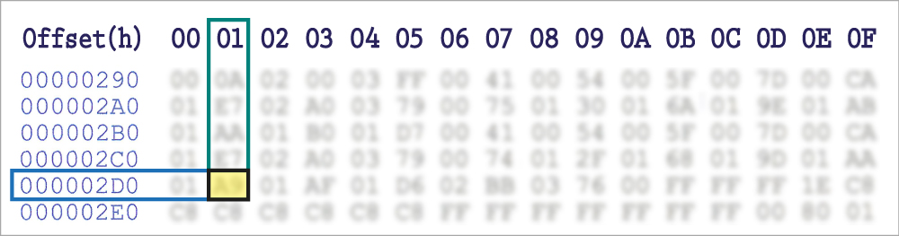
– act on the location 02B1 for the left-hand side display;
– act on the location 02D1 for the right-hand side display.
Please note that decreasing these locations by 1 HEX unit, the variation will be + 0,0132 V or vice versa.
NOTE: If not familiar with hexadecimal calculation, it is possible to use the calculation tool in the box below, simply typing in the values.
SEPDISP71 - EEPROM 24C16
Calculation of the new values of the locations
Left-hand side display
Right-hand side display
* How to identify the locations 02B1 and 02D1 values on the EEPROM programmer
Once these modifications have been done, measure again the voltage between the points indicated in picture 5 and 6 and check that it actually is between 7.29V and 7.31V, if not, increase or decrease the locations until the value is as close as possible to 7.30V.
Video Tutorial
How to repair Mercedes SL-Class R230 dashboards with Minitools SEPDISP71 LCD screens