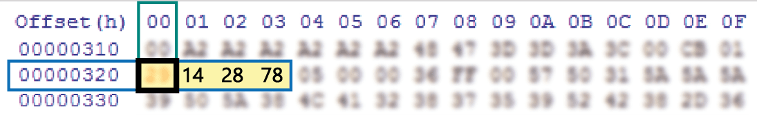
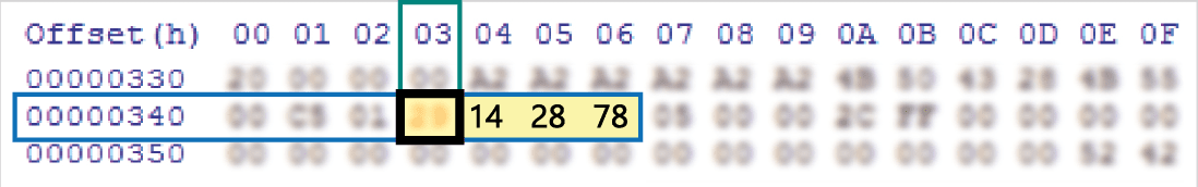
*Come individuare il valore della locazione 0320 e della locazione 0343 sul programmatore EEPROM
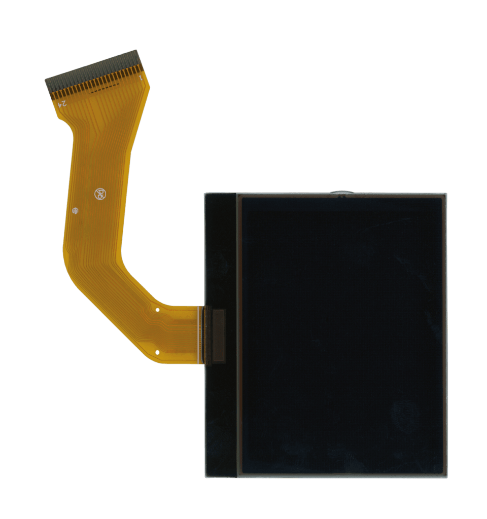
Before installing the new SEPDISP27 display, please read the following instructions carefully.
DO NOT SKIP ANY STEPS.
NOTE:
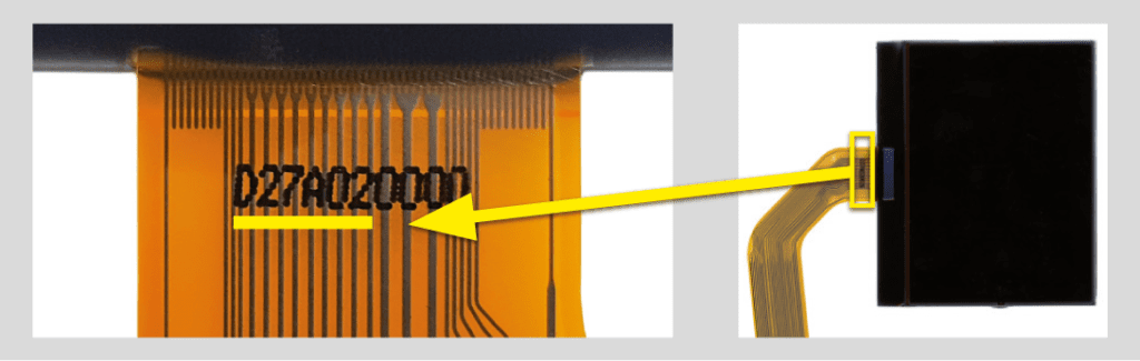
The following instructions are for SEPDISP27 displays marked with D27A02XXXX serial numbers on the FPC (see picture beside).
• Replace the display in an ambient temperature of 25 °C.
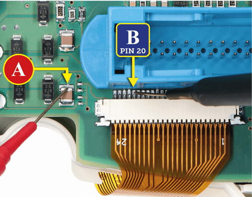
• After replacing the LCD, switch on the cluster (pin no. 1 positive, pin no. 24 negative)
• If you have a multimeter with needle probes, measure the voltage between A and B points on the rear of the board (see
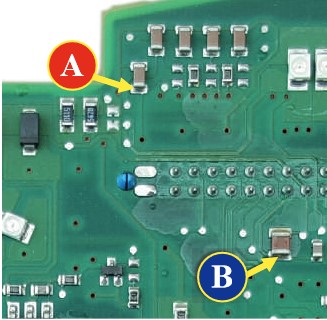
picture 1), OTHERWISE remove the pointers and the front panel and measure the voltage between A and B points on the
front part of the board (see picture 2).
• If the voltage measured is between 7,0V and 7,2V, no modification is necessary;
• If the voltage detected is instead lower than 7,0V or higher than 7,2V, it is necessary to do the modification described in the
following paragraph “EEPROM MODIFICATION“
NOTE: For this modification on the instrument clusters,
it is necessary to use an EEPROM programmer.
We recommend our SEP-EECLIP.
• First, set the programmer reading in 8 bit hexadecimal (HEX).
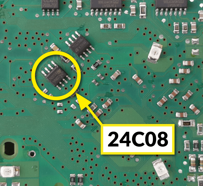
• Make a backup of the 24C08 EEPROM, which is on
the cluster (picture 3).
To reach a voltage between 7,0V and 7,2V, it is necessary to modify the value of 0320 location OR the one of 0343 location; to identify which location to act on, locate the group of 3 consecutive values: “14, 28, 78”. The value to be modified is always the one before the group just mentioned.
Please note that increasing or decreasing these locations by 1 HEX unit, the variation will be +/- 0.1V.
If not familiar with hexadecimal calculation, it is possible to use the calculation tool in the box beside, simply typing in the values.
Once these modifications have been done, measure again the voltage between A and B points and check that it actually is between 7,0V and 7.2V. If not, increase or decrease the location until the value is as close as possible to the right range.