- 06/09/2022
MERCEDES G-CLASS W463 AND C-CLASS W203 INSTRUMENT PANELS LCD PIXEL REPAIR
Guide to repair Mercedes C-Class W203 – S203, C-Class Sportcoupé CL203 and G-Class W463 instrument clusters with faded or dim display
Is the Mercedes G-Class W463 MFD multifunction display fading? Is the Mercedes C-Class W203 instrument cluster display dim? This issue on Mercedes C-Class and G-Class speedometers is usually related to high temperatures: it can happen for example when the car has been left under the sun on a warm day. Rather than replacing the entire instrument cluster, Minitools offer an alternative and less expensive solution: replacing Mercedes C-Class W203 and G-Class W463 instrument panel display only, fixing the issue.
With Minitools SEPDISP06 replacement LCD you can replace the faulty MFD display of Mercedes W463 (2001-2007 models), CL203, S203 and W203 (2000-2004 pre-facelift models) and repair the dashboard!
Repairing the instrument cluster rather than replacing is less expensive, easier and, most importantly, avoids the disposal of the device, respecting the environment.
Here’s a step-by-step DIY guide for Mercedes C-Class W203 – S203, C Sportcoupé and G-Class W463 speedometer LCD screen replacement
- Remove the faulty instrument cluster from the car;
- With a pry tool or spudger, leverage on the plastic clips on the side of the panel and remove both the rear and the front cover;
- Remove the LCD display bezel and the side button;
- Open the connector and unplug the FPC from the PCB on the rear part of the panel;
- From the front one undo the display and remove it;
- Get the new display, peel off its protective films and place it on its base, securing it;
- Plug the FPC in its connector and close it;
- Switch on the panel (pin 1 negative, pin 5 and 6 positive);
- There are 2 different PCB versions, identify the one of your cluster and measure the voltage in the points indicated in the picture below (measure it while the dashboard is switched on).
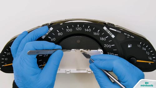
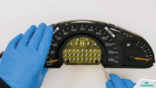
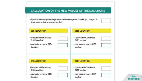
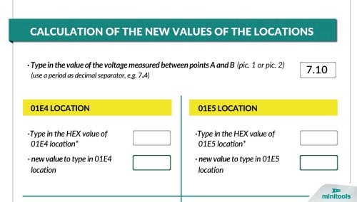
If the voltage measured is between 7,7V and 7,8V the problem is solved, and you can re-assemble the panel. If it is lower than 7,7V or higher than 7,8V, you will have to do a modification of the EEPROM 93C86 with a specific programmer in order to adjust the voltage and the display contrast.
- Remove the display as before;
- Take out the backlight unit that is underneath the display;
- With a torx T10 screwdriver, undo the screws of the white plastic base and remove it;
- Carefully undo the circuit with the backlights LEDs using the tweezers;
- Remove the black plastic cover under the circuit;
- Take off the middle needle;
- Undo the PCB from the panel and lay it to reach the side where the EEPROM 93C86 is located;
- Thermally insulate the components around the EEPROM 93C86 with some Kapton tape;
- With a hot air de-soldering iron, de-solder the EEPROM;
- Clip the EPPROM connecting it to the programmer and set the reading in hexadecimal;
- IMPORTANT! Make a backup of the EEPROM before starting the modification;
- Identify on the EEPROM the locations 01E4, 01E5, 01E6 and 01E7 highlighted in the picture below;
- Open the PDF on the product page where you’ll find a calculation tool to help you with the modification;
- Note: please use the values related to your faulty instrument cluster, those were going to use are just an example. Type in the voltage measured before in the first box on the upper-right side of the calculation tool, in this case we; ll write as an example 7,10V;
- Type in the value of 01E4 location in its related box on the calculation tool. In this case, for example, the value of the location is 16.
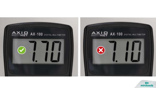
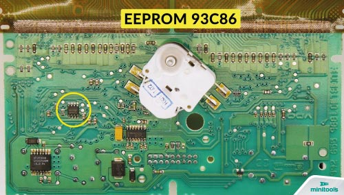
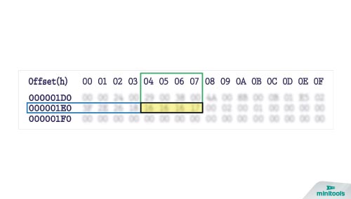
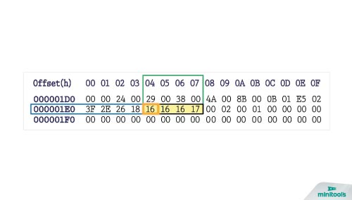
The calculation tool will automatically get the new value, in this case 1D, to insert in the location on the EEPROM; - Type in the other locations values in their related boxes on the calculation tool;
- Type in the new values obtained with the calculation tool in the related locations on the EEPROM;
- Save the file just modified and upload it on the EEPROM;
- Un-clip the EEPROM from the programmer;
- Before soldering it back, remove the tin excess from the PCB with a solder wick;
- Clean the pads with some solvent;
- With the aid of the tweezers, solder the EEPROM on the board with a soldering iron with conical tip at 350° C;
- Clean with some solvent and remove the Kapton tape;
- Re-attach the board on the panel;
- Put back the needle. Then the plastic cover and the LEDs circuit;
- Fit and secure the white plastic base, tightening the screws (avoid tightening them too tightly as the circuit underneath my get damaged);
- Put back the backlight unit;
- Switch on the dashboard again, and, with the multimeter, recheck the voltage between the points indicated in the picture.
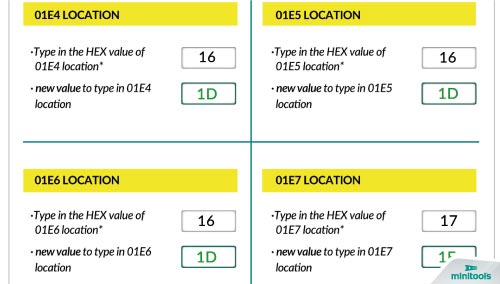
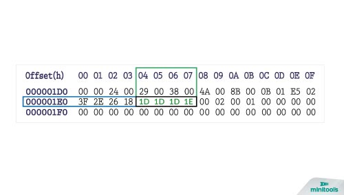
If the voltage, as in this case, is now between 7,7 and 7,8V, the modification was successful. If the voltage has not changed after the EEPROM modification, we recommend contacting us by e-mail at [email protected] ;
- Put back the display bezel;
- Making sure not to damage the resistor on the FPC, fit back the rear cover of the cluster;
- Put back the side button;
- Fit the front cover;
- Put back the cluster in the car.
Perfetto! Problem solved!
To help you with the repair, Minitools technicians have made a video tutorial about how to fix the faded LCD screen issue of Mercedes C-Class and G-Class dashboards:
Mercedes C-Class W203 and G-Class W463 speedometer dim display replacement – DIY tutorial
Some codes of Mercedes C-Class S203 – W203, C-Class Sportcoupé CL 203 and G-Class W463 instrument clusters that can be repaired with Minitools SEPDISP06 LCD screen:
110.080112/006; A 203 540 86 11; 110.080.111/009; A 203 540 73 11; 110.008.896/011; A 203 540 07 11.