27 May 2025
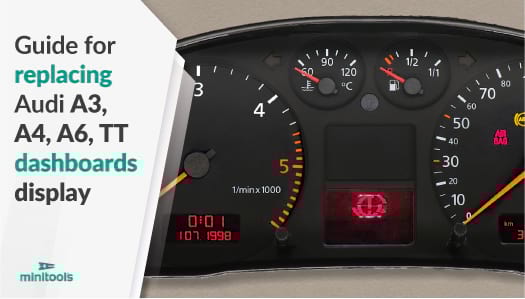
Is the Audi A4 B5 instrument panel display unreadable? Is the Audi A6 C5 speedometer display fading? Is the Audi A3 8L dashboard screen blank? Is the Audi TT 8N instrument cluster display not working? Replace it with Minitools display SEPDISP09.
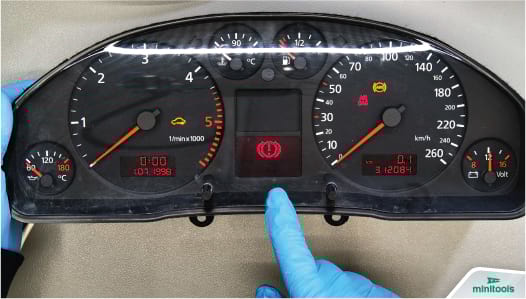
Often, those instrument panels LCDs can have failing or dead pixels, fade, go blank or show flickering segments, and therefore be difficult or impossible to read.
The following guide will explain how to fix Jaeger and Magneti Marelli instrument clusters of Audi A3 8L (1996-2003); Audi A4 B5 / 8D (1994-2001); Audi A6 C5 / 4B (1997-2004); Audi TT 8N (1998-2006), replacing the original display with Minitools part SEPDISP09.
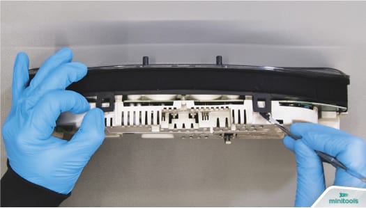
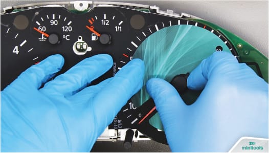
Undo the back screws of the cluster and, with the aid of the spudger, release the front part.
Fit the gauge overlay protective disc under the speed and RPM needles and remove them rotating them anticlockwise.
With the aid of the gauge face protective disc and the spudger, remove the smaller pointers which will be gently lifted and pulled out.
Take off the back part as well.
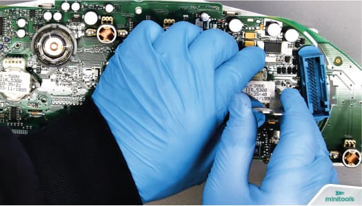
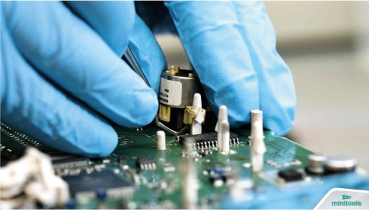
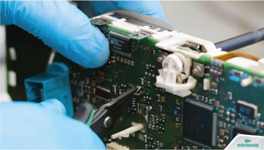
To remove the two larger stepper motors, insert the tweezers in the respective side holes, then bring them closer as shown (SEE GALLERY).
The smaller motors will be pulled out with the aid of the curved tip probe.
Undo the metal frames of the side screens and the plastic clips.
Release the board.
Remove the reset button.
Release the screen from its base.
De-solder the FPC with a hot air de-soldering iron.
Using a soldering iron with chisel tip and de-soldering braid, remove any residual solder.
Clean with some solvent.
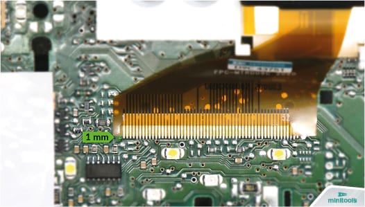
Starting from the first pin on the left, position the FPC of the Minitools display leaving 1 mm gap as shown (SEE GALLERY), and secure it on the board with a few soldering spots.
N.B. Using flux is not recommended.
Then, solder it one pin at a time with a soldering iron with needle tip and thin solder wire*.
*0.3 mm solder wire
Clean with solvent
Peel the back film off the new display and fit it in its base.
The FPC has to be folded gently underneath as shown (SEE GALLERY).
Remove the front film of the LCD as well.
Insert the reset button.
Fit the board to the front base with the gauge overlay and secure it.
Put each motor back gently pressing them. Then, fit the back part of the cluster.
Switch on to the dashboard.
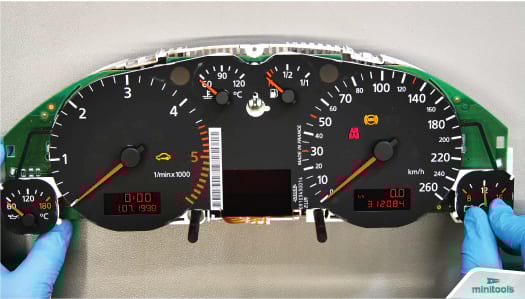
With the cluster switched on, insert the pointers in their original place, the voltmeter one has to be placed directly pointing 12 V (SEE GALLERY).
Switch off and then back on the cluster, to check the correct positioning of the needles.
Fit the front part.
Perfetto! Problem solved.
Is the Audi A4 B5 instrument panel display unreadable? Is the Audi A6 C5 speedometer display fading? Is the Audi A3 8L dashboard screen blank? Is the Audi TT 8N instrument cluster display not working? Replace it with Minitools display SEPDISP09.
Often, those instrument panels LCDs can have failing or dead pixels, fade, go blank or show flickering segments, and therefore be difficult or impossible to read.
The following guide will explain how to fix Jaeger and Magneti Marelli instrument clusters of Audi A3 8L (1996-2003); Audi A4 B5 / 8D (1994-2001); Audi A6 C5 / 4B (1997-2004); Audi TT 8N (1998-2006), replacing the original display with Minitools part SEPDISP09.
Undo the back screws of the cluster and, with the aid of the spudger, release the front part.
Fit the gauge overlay protective disc under the speed and RPM needles and remove them rotating them anticlockwise.
With the aid of the gauge face protective disc and the spudger, remove the smaller pointers which will be gently lifted and pulled out.
Take off the back part as well.
To remove the two larger stepper motors, insert the tweezers in the respective side holes, then bring them closer as shown (SEE GALLERY).
The smaller motors will be pulled out with the aid of the curved tip probe.
Undo the metal frames of the side screens and the plastic clips.
Release the board.
Remove the reset button.
Release the screen from its base.
De-solder the FPC with a hot air de-soldering iron.
Using a soldering iron with chisel tip and de-soldering braid, remove any residual solder.
Clean with some solvent.
Starting from the first pin on the left, position the FPC of the Minitools display leaving 1 mm gap as shown (SEE GALLERY), and secure it on the board with a few soldering spots.
N.B. Using flux is not recommended.
Then, solder it one pin at a time with a soldering iron with needle tip and thin solder wire*.
*0.3 mm solder wire
Clean with solvent
Peel the back film off the new display and fit it in its base.
The FPC has to be folded gently underneath as shown (SEE GALLERY).
Remove the front film of the LCD as well.
Insert the reset button.
Fit the board to the front base with the gauge overlay and secure it.
Put each motor back gently pressing them. Then, fit the back part of the cluster.
Switch on to the dashboard.
With the cluster switched on, insert the pointers in their original place, the voltmeter one has to be placed directly pointing 12 V (SEE GALLERY).
Switch off and then back on the cluster, to check the correct positioning of the needles.
Fit the front part.
Perfetto! Problem solved.