SEPDISP33
Installation instructions for Ford Focus, C-Max, Kuga instrument clusters LCD display
WARNING: THIS PROCESS IS RECOMMENDED ONLY TO EXPERT AND QUALIFIED STAFF
Before installing the new SEPDISP33 display, please read carefully the following instructions. Our technicians, for illustrative purposes only, have made a video tutorial about how to repair the instrument cluster.
DON’T SKIP ANY STEP.
Necessary operations:
- Replace the display (see steps 2, 3 and 4)
- Replace the capacitor (see steps 5)
- Replace the resistor (see step 6)
1
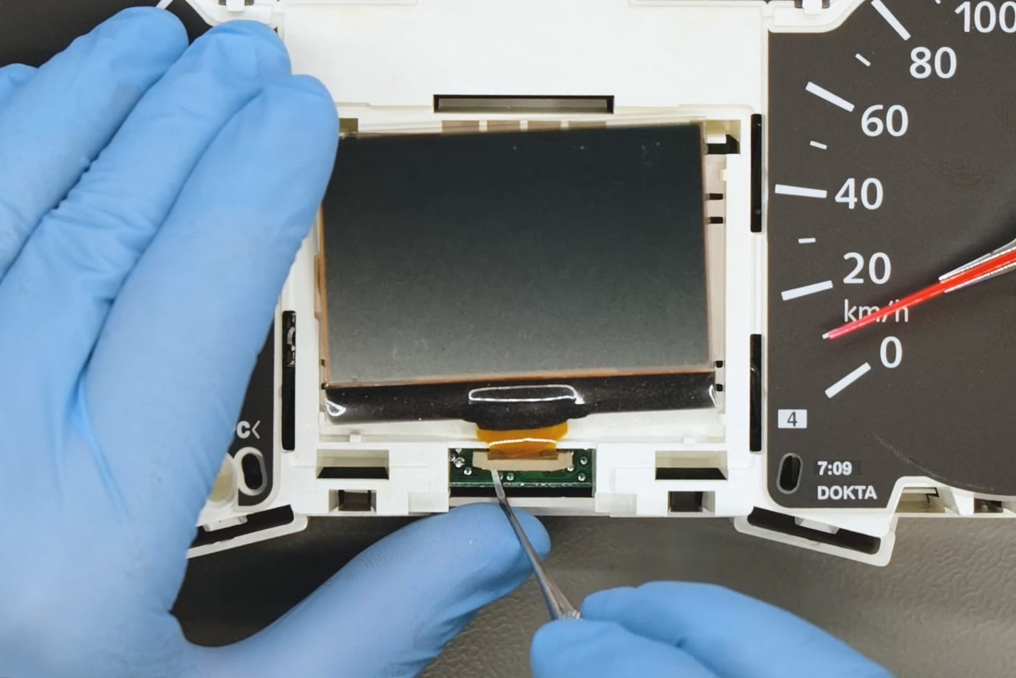
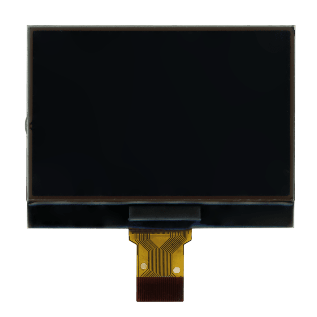
Open the instrument cluster and remove the faulty display.
2
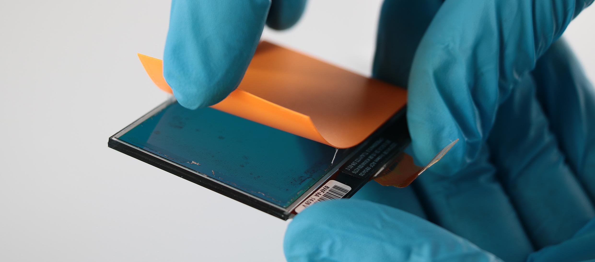
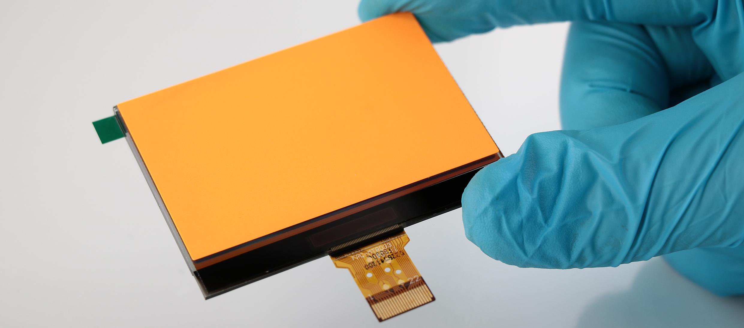
Remove the orange film from the back of the original display and place it on the back of the new SEPDISP33 display
3
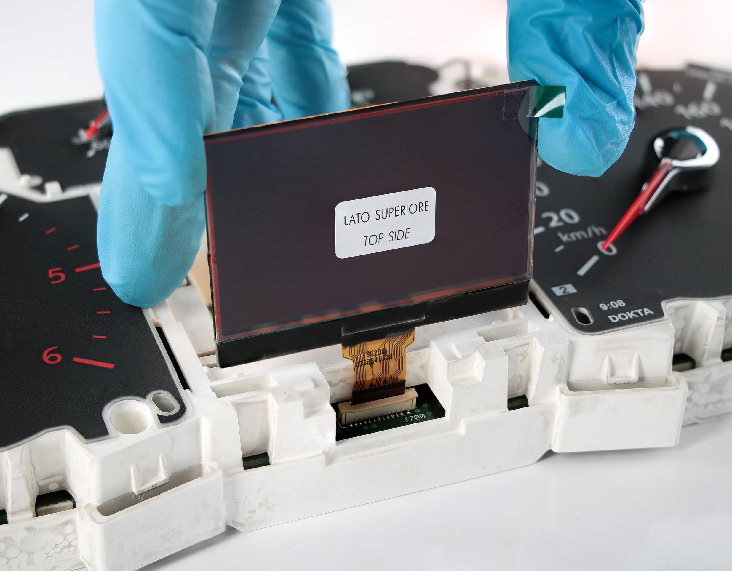
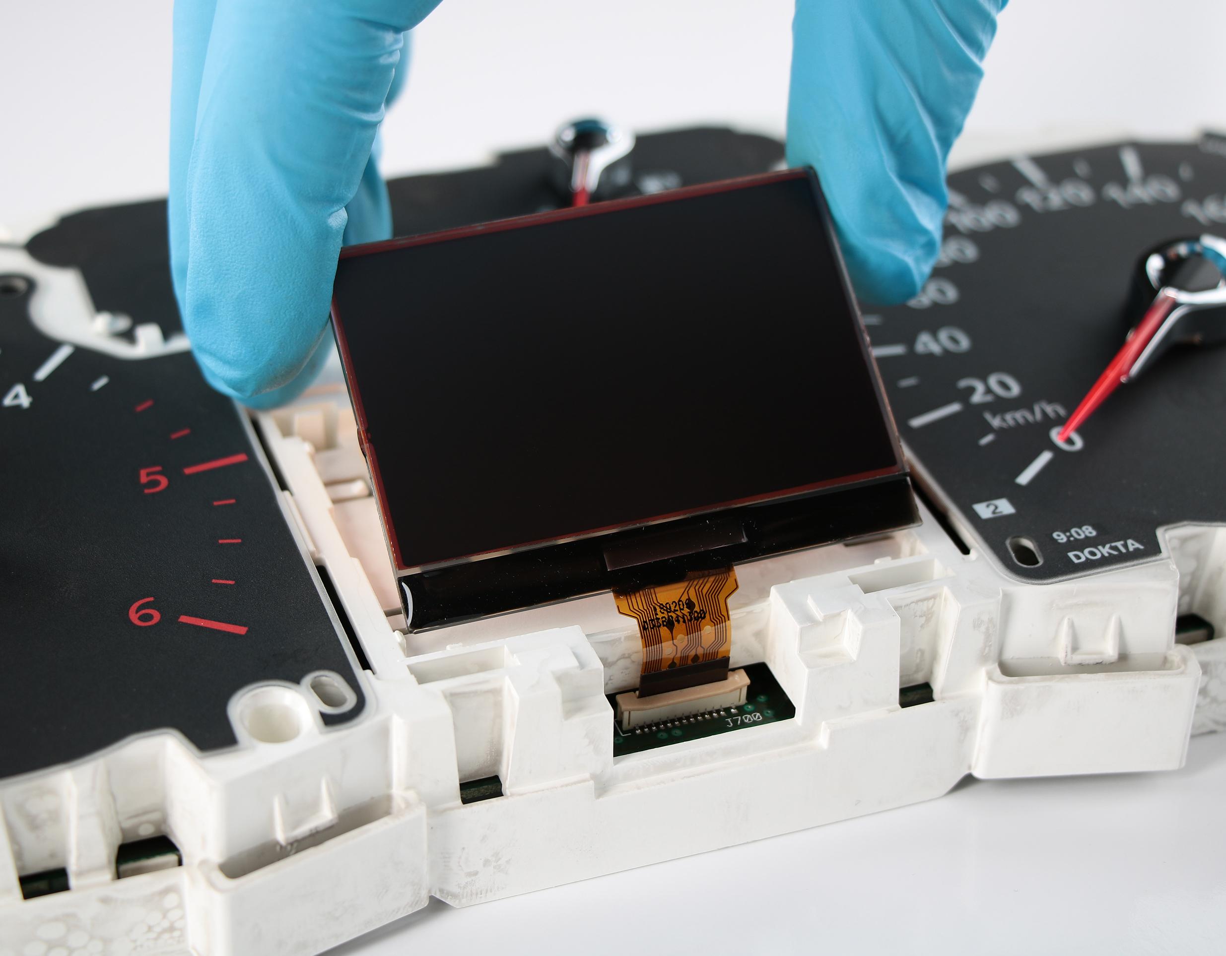
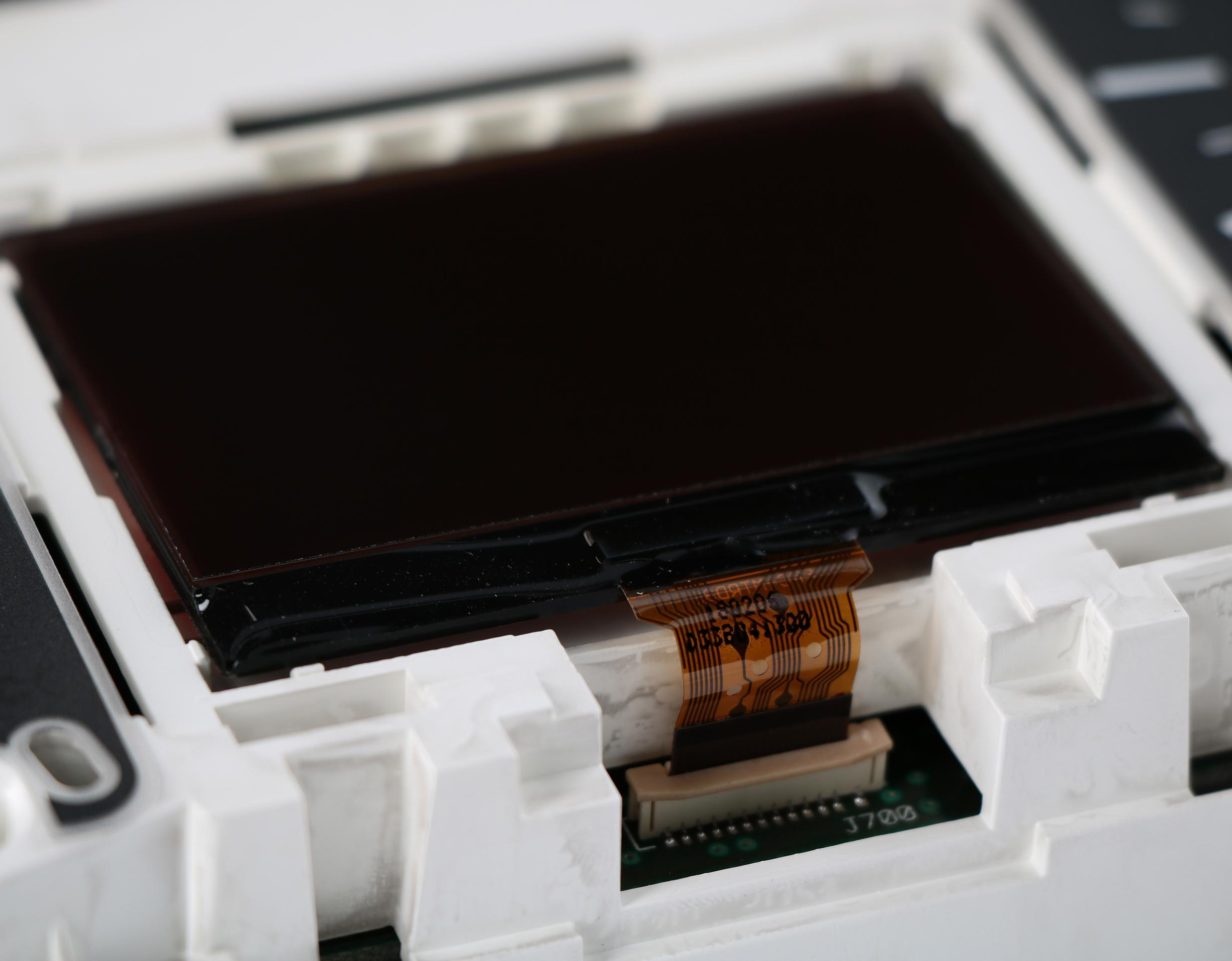
Holding SEPDISP33 display upright, insert the FPC in its connector until it is properly fitted.
ATTENTION: this procedure must be carried out before positioning
the display in the dashboard plastic housing.
4
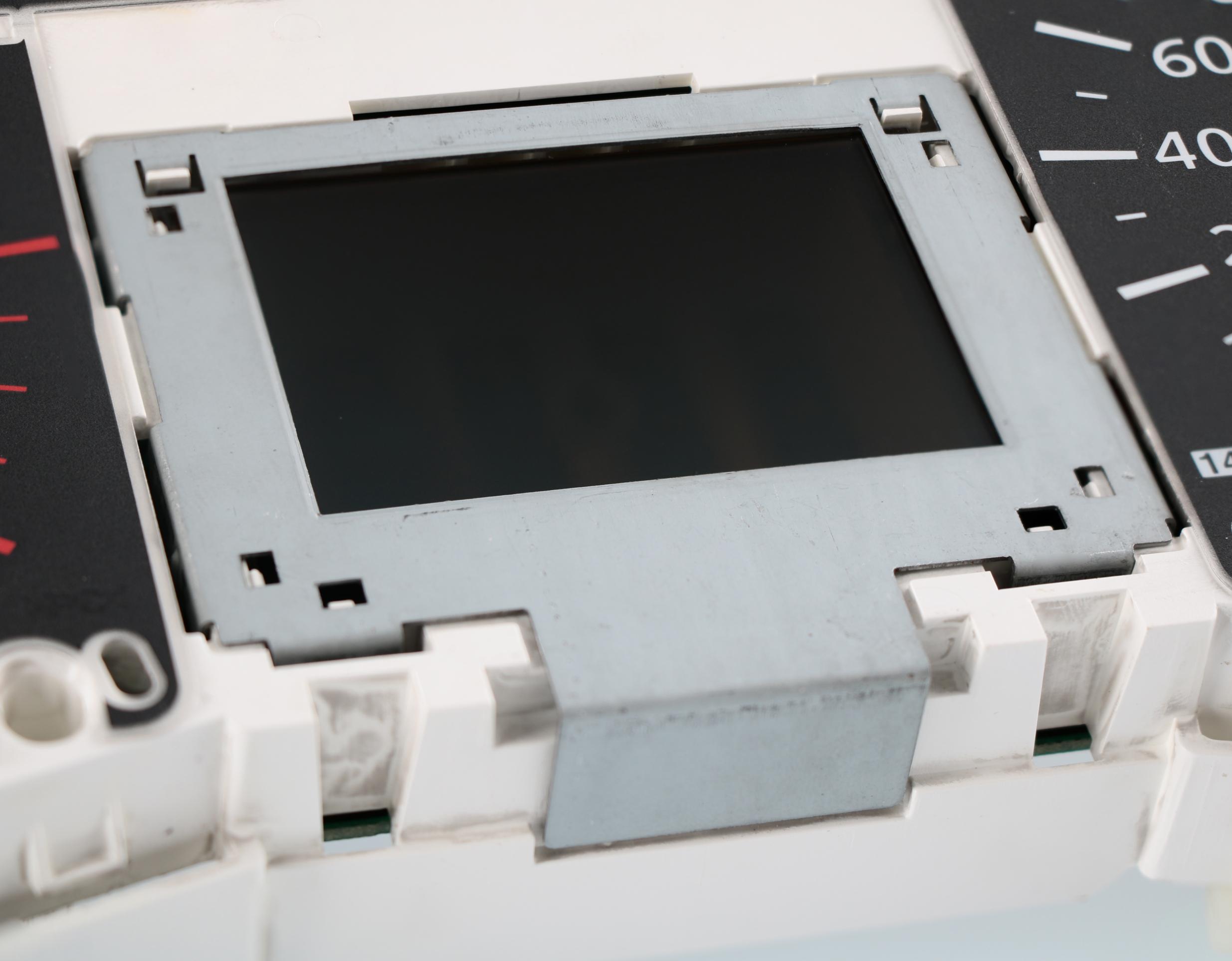
Carefully position the display in its plastic housing until it is in the correct position. Then secure the display in place with the metal frame.
5
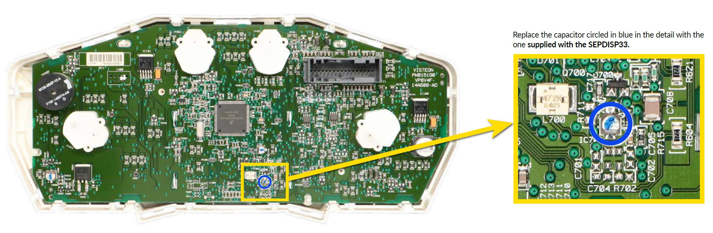
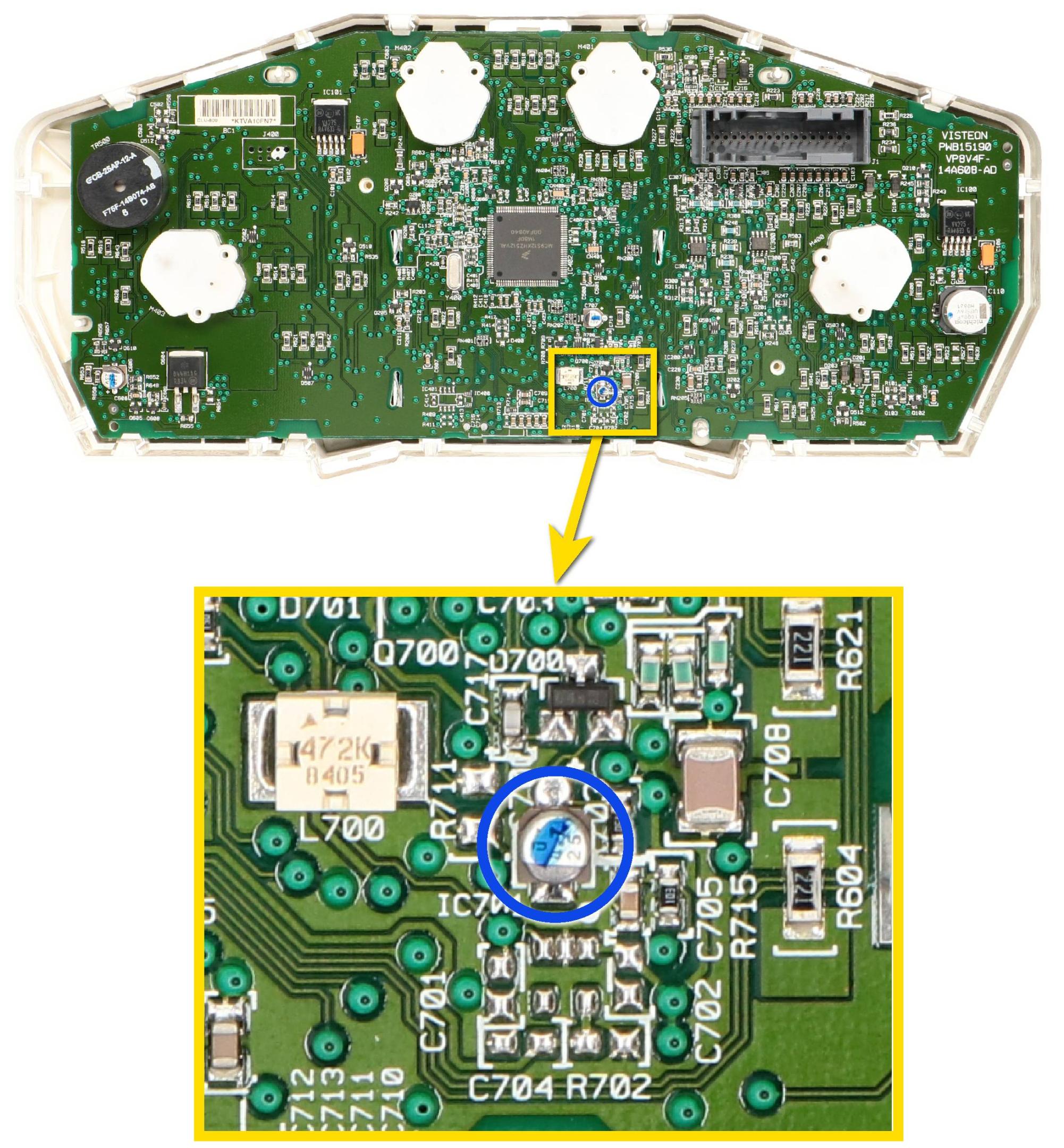
Replace the capacitor circled in blue in the detail with the
one supplied with the SEPDISP33.
6
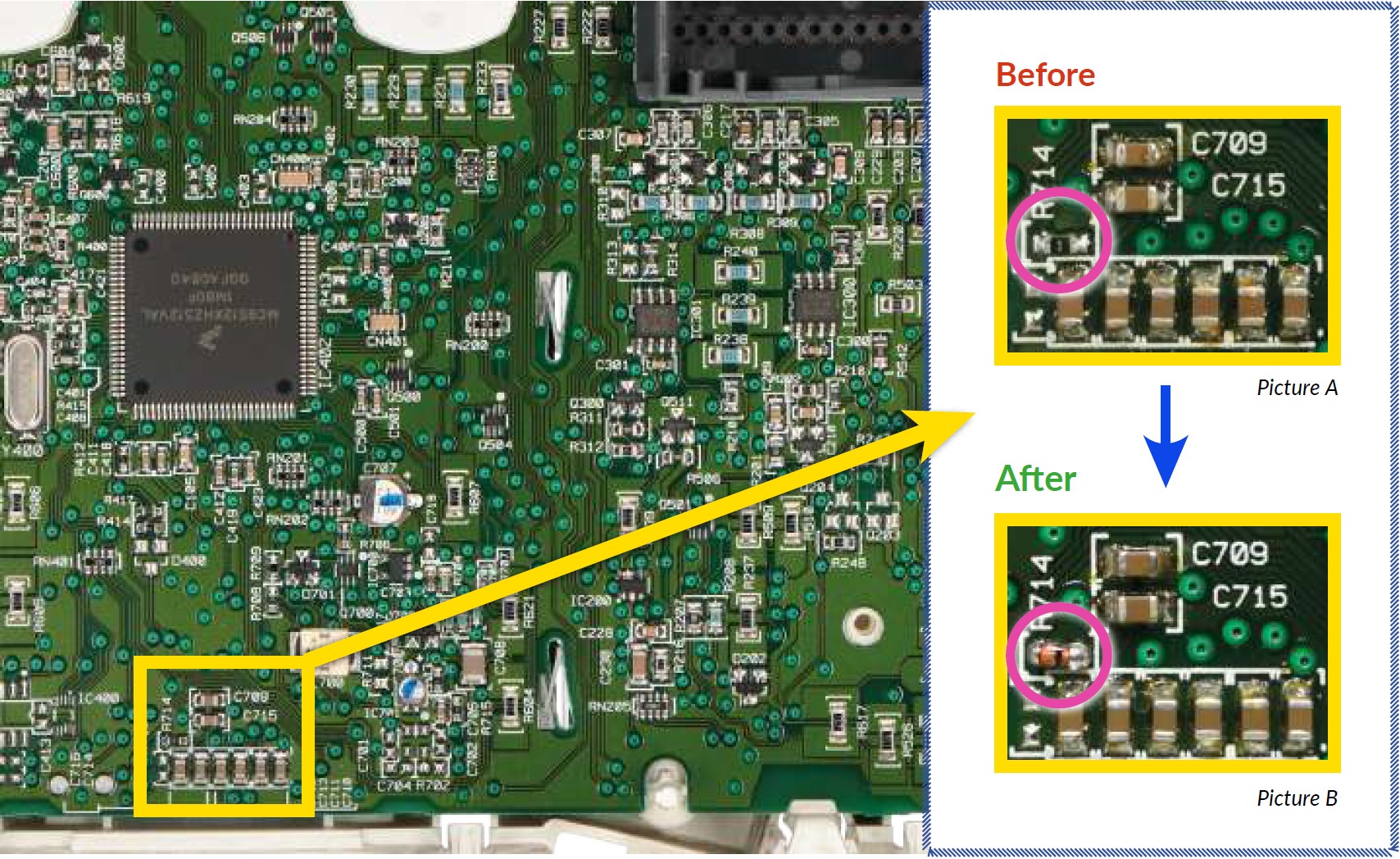
After installing the SEPDISP33, replace the 0R resistance (picture A) with the MCL4148-TR diode (picture B) included in the package. Ensure the diode is fitted the right way round.
7
Before re-assembling the instrument cluster, power it up on a test bench with the Minitools conncetor SEP-PA006 to verify the correct functioning of the SEPDISP33 display. If it doesn’t work correctly, make sure all steps listed have been followed.
If the problem persists after the check, please contact us sending an e-mail at
[email protected].